Challenging hydrogeology on Fort Wayne CSO drive 04 Mar 2021
With hydrostatic pressure at up to 6.5 bar and groundwater inflows in the range of 5,000-10,000 gals/min (0.32-0.63m3/sec), construction of the 4.6 mile x 16ft i.d. (7.5km x 4.9m i.d.) CSO interceptor project for Fort Wayne City Utilities in Indiana faces challenging conditions. Main contractor, Salini Impregilo-Lane JV, has so far excavated 3 miles (4.8km) of the alignment at 200ft-240ft (61m-73m) deep, after launching its 19ft (5.8m) diameter Herrenknecht slurry TBM in April 2019. The drive is expected to complete by mid-April 2021.
The interceptor project is part of a US$240 million Federally-mandated programme of works and will reduce discharge from CSOs into the St Marys and Maumee rivers by 94% or 1 billion gallons, as well as reducing sewage back-up in neighbourhood streets and in homes. In addition to Salini Impregilo-Lane, the City of Fort Wayne contracted Black & Veatch for tunnel design and Jacobs as construction manager.
“The high groundwater inflow and pressure is the main reason a slurry machine was selected,” said Francesco Chiappalone, Technical Manager at Salini Impregilo-Lane, on a recent call with Lance Waddell, Salini Impregilo-Lane Project Manager, and TunnelTalk. “We are driving through dolomite limestone formations, which is not typical geology for a slurry TBM, but it has been a good choice. Our production rate has been on target and we have been able to manage the water inflow effectively.”
The use of a slurry TBM has also helped with muck removal on a drive with only one working shaft and that started heading west, before curving slowly through 90° and will complete the drive heading south (Fig 1). “As muck is transported out through the slurry circulation system, the curved alignment does not pose a challenge,” said Chiappalone.
In addition to the hydrogeological challenges, the TBM has also had to excavate through changing stretches of massive dolomite and a reef-type limestone formation with some mixed-face conditions of both (Fig 2). “This has affected penetration rates and advance speed, as well as causing some impact damage to the cutting tools, although general wear on the cutterhead has not been high,” said Chiappalone.
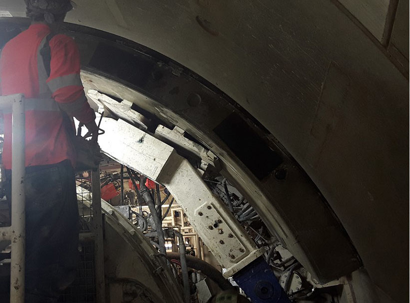
To reduce time spent on and the risks involved with cutterhead interventions, the contractor decided to perform maintenance at atmospheric pressure, rather than using hyperbaric operations. “The TBM is equipped with dewatering ports through the front and middle shields that allow us to dewater the face, discharging the water into the tunnel invert. Some of these ports can also be used for probe drilling, as necessary,” said Chiappalone. “After we have dewatered the face, we are able to open the access doors at atmospheric pressure to perform maintenance.”
In the event that maintenance is required in an area that cannot be freely dewatered, and with no hyperbaric locks in the machine, there is a design in place for pre-excavation grouting to allow man entry under atmospheric conditions, but so far this has not been required.
Inspection of the cutting tools takes place every two to three weeks with each inspection requiring machine downtime of at least day. This is significantly less time than would be required for hyperbaric interventions. “The cutterhead interventions can be done more quickly in free air atmospheric conditions,” said Chiappalone, “so we have saved time and money with this approach, and have made interventions safer.”
The drive is lined with steel fibre-reinforced concrete segments, each 1ft thick x 5ft wide (30cm x 1.5m wide), with 35.6kg/m3 of reinforcement to concrete. Each ring comprises four trapezoidal segments, weighing up to 4 ton, plus a key and counter key, and weighs a total 20 ton when assembled. Segments are manufactured in Ohio by the CSI Tunnel Systems-Forterra JV, transported to site by truck and lowered to the supply train by crawler crane.
The 33ft (10m) diameter x 240ft (61m) deep working shaft is one of three large-diameter shafts on the US$188 million project (Fig 1) and is adjacent to the 69ft (21m) x 240ft (61m) deep pumping station shaft. The connection between the two shafts was excavated by drill+blast with rock bolt and mesh support. Instead of segmental lining, a large steel pipe will be installed in this section, which will then be backfilled with cellular grout as the concrete shaft liners are completed.
The 29ft (8.8m) diameter retrieval shaft will function as one of eight drop shafts on the scheme and was originally designed to be 180ft (55m) deep. It was shortened to 120ft (36.5m) to reduce the risk of high water inflow similar to that experienced during the excavation of the working and pump shafts. The alignment was further optimised in discussions with the project owner to increase the radius of multiple curves in order to reduce stresses on the segmental lining and bring the route closer to the drop shaft locations and reduce the length of connecting adits.
Shaft and adit construction
The main shafts were constructed by Salini Impregilo-Lane as part of the tunnel contract using diaphragm walls through the 70ft (21m) overburden, followed by drill+blast to depth, supported by rock bolts and shotcrete, with a final cast-in-place concrete lining to be installed after the TBM has broken through and the adits are complete.
The additional drop and vent shafts range from 2ft (600mm) to 8ft (2.4m) in diameter and are excavated by blind bore drilling with a ductile iron or spun fibreglass-reinforced polymer mortar pipe lining. The drop shafts and other near-surface structures, including the diversion structures to the drop shafts, are currently under construction.
The drop shafts will be linked to the main alignment by drill+blast adits of a cross section of 9ft x 9ft (2.7m x 2.7m) and vary in length between 50ft and 180ft (15m-55m). “The original design of the adits and deaeration chambers included a cast-in-place lining but this was redesigned to be a spun fibreglass pipe similar to the drop shafts, to further mitigate project risks due to water inflow,” said Waddell. Due to the hydrogeological conditions, pre-excavation grouting will be required to construct the adits with any residual groundwater inflow pumped out via the main alignment.
A final change to the Salini Impregilo-Lane scope of work was to reassign installation of the cast-in-place lining of the working and pump station shafts to the joint venture. “Originally, only the lining of the retrieval shaft was part of our contract, but as part of a project improvement plan negotiated with the owner, the liners were removed from the pumping station contract and added to our contract,” said Waddell. “This allows us to progress more of the work concurrently, helping to meet the Federally-mandated deadline to complete the project.”
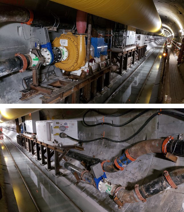
Construction of the shaft lining will require contact grouting through and behind the liners, as or shortly after they have been poured. Until the lining is in place, the inflow from the shafts and TBM excavation is being pumped out. “We have had to improve and install additional pumps to deal with the water volume,” said Chiappalone.
Despite the challenges posed by the high hydrostatic pressure and groundwater inflows, the conditions have been managed by the project team to keep TBM excavation progressing. Both Waddell and Chiappalone bring experience of similar conditions to the project with Waddell being part of the Lake Mead intake project in Las Vegas, where hydrostatic pressures reached 15 bar, and Chiappalone working on the Red Line North in Doha, where a TBM and shaft encountered similar high water inflow conditions.
Working through a pandemic
The other main challenge for the project team has not been something they could prepare for. “No-one has any experience of working through a pandemic,” said Waddell. “We learned as we went and were diligent at following the State and Federal Centers for Disease Control Guidelines.”
This has required changes to working patterns, particularly at shift change to help keep people separated, as well as monitoring worker health status before they enter the site. “Thus far we have had about nine days of delay due to the pandemic, but we are through that and back on track,” said Waddell.
Construction is now progressing to meet the mandated completion deadline of December 2023 and to provide Fort Wayne with a viable option to reduce overflows into the St Marys and Maumee Rivers for many decades to come.
References
- DigIndy progresses to final bore – TunnelTalk, December 2020
- Replacement TBM needed to finish St Louis CSO drive – TunnelTalk, January 2021
- TBMs complete Doha Metro Red Line North – TunnelTalk, March 2016
- Watering up the hard-fought Lake Mead Tunnel – TunnelTalk, September 2015
- Learning from difficult rock TBM drive experiences – TunnelTalk, January 2021
|
|
|
|
|
Add your comment
- Thank you for taking the time to share your thoughts and comments. You share in the wider tunnelling community, so please keep your comments smart and civil. Don't attack other readers personally, and keep your language professional.


