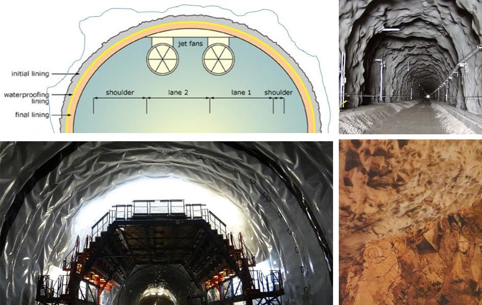
In taking a broad look at tunnel lining options, cost, construction time, and the CO2 implications of concrete consumption are each of significant concern. For many decades a method has been in use that effectively minimizes cost and time and the use of concrete. The method is known as NMT, the Norwegian Method of Tunnelling. It is based on application of the Norwegian Q-system to design the rock support and emphasizes a single-shell shotcrete final and permanent lining. Its characteristics distinguish it from double-shell options that include final load-bearing and often steel-reinforced concrete linings as the permanent finish. Such a method is more expensive, uses more concrete, can take longer to build, and usually requires a larger labour force.

A common problem in underground excavation is the incidents of profile over excavation and drill+blast overbreak. Significant over break is inevitable if the Q-system parameters show a ratio of joint sets (Jn) to surface roughness (Jr) equal to or more than 6 (Fig 2). For example, in a situation of three joint sets and planar joints where the ratio is Jn 9 and Jr 1.5, over-break is common and increases the volume of concrete required to complete a double shell lining. When using the NMT single-shell S(fr) lining option, over-break is less of an issue. The area of the excavation perimeter is greater with over-break, but the over-break is not and should not be filled. The rock mass, assisted by systematic bolting and shotcrete, takes the major load.
Single-shell designs provided the final, permanent tunnel linings for road, rail, hydropower, water transfer, mine access and mine roadway developments as well as for large caverns for storage of oil or food, for hydropower machine and transformer halls.
In each case, NMT based tunnels and caverns are made stable via application of the Q-system of rock mass quality estimation that encompasses a rock mass quality scale from 0.001 - equivalent to a serious fault zone, where NMT may also need a local concrete lining - to 1000 which is equivalent to massive unjointed rock where careful blasting can remove the need for shotcrete, but in practice is applied perhaps with one layer of S(fr).
In typical rock masses where tunnels and caverns are excavated, rock mass quality will lie on either side of mid-range or closer to Q = 1 which is described as poor quality with an associated mid- range bell-shaped distribution of RQD. These conditions would need combinations of corrosion-protected rock bolts and high-quality fibre-reinforced shotcrete, with stainless-steel or polypropylene fibres. Systematic high-pressure pre-injection grouting using micro-cement and micro-silica may be required to control water inflow to create essentially dry tunnels with limited inflow of approximately 1-2 liters/minute/100 linear metres of tunnel which can be dried out by the ventilation air in ventilated facilities. Systematic pre-injection grouting may add 20-25% to the starting cost of the NMT excavations. A note is that a central value of Q = 1 or poor, often correlates with approximately 1 Lugeon or a permeability of 10-7m/sec. In such cases inflow would be unacceptable and would require pre-injection grouting.

A source of risk for double-shell lining designs is the reliance on a drainage fleece and waterproofing membrane to control water seepage. Depending on the cross section of the excavation, there may be 12km to 15km of membrane welds/km of tunnel. Should a leak through the final concrete lining occur, exactly where it is coming from is hard to judge, as it may only appear at the closest joint.
In support of single-shell designs, it surprises many that S(fr) has a lower matrix permeability compared to mass concrete – maybe 10-11 to 10-12m/sec, (confirmed by tests in 1980) – and much lower single or double-layer permeability than cast concrete linings, due to the absence of radial joints in the S(fr). To achieve high impermeability of S(fr), tight quality control and good quality additives are required. Highest unit prices for additives and fibres ensure the fastest, cheapest and safest tunneling.
The relative time and costs of Q-value based good quality S(fr) + high quality rock bolting, such as systematic patterns of bolting using corrosion-protected CT bolts with a PVC sleeve can be illustrated based on the analysis by Professor Steinar Roald of 50km of Norwegian and Swedish tunnel projects (Fig 4). The lower plateaux are due to minimal support and reinforcement. Whatever the rock mass quality the double-shell cost level is high in the left corner of the graph due to the processes involved and the materials used. The systematic double shell concept will be faster, per meter, than non-systematic local zones of cast concrete in NMT projects, since this local heavy support has to be applied where rock conditions are challenging, hence the approximately estimated lowered time box in the left diagram of Fig 4.
A typical 0.4 to 40 range of Q is illustrated by the NMT calculations box. Due to the demands of high-volume concrete, plus drainage membrane, the relative cost of a double-shell design is higher than for NMT. It is as if the rock mass quality for a double-shell design is exceptionally poor, which is only the case, for example, in some tunnels in the Alpine region, in the lower Himalayas and in countries with younger geologies.
The same trends of relative cost versus Q as in Fig 4 are found when directly applying the Q-system support recommendations, for a range of road tunnels, of varied cross-section, with material costs, blasting and 4km of muck transportation included (Fig 5). Neither systematic pre-grouting nor the frequently used alternative for road and rail tunnels in Norway of erecting free standing precast concrete elements that are bolted to the rock with a seal through the membrane that lies on their extrados, are included in Fig 5.
|
|
|
|
|