Choosing right fibre for SFRC precast segments Aug 2020
Fibre reinforced concrete is a composite material characterised by a cement matrix and discontinuous discrete fibres, which can be steel, polymers, carbon, glass or natural materials. The characteristics of the materials used, and their dosage, affect the final properties of the FRC.
Fibre reinforced concrete (FRC) is also influenced significantly by a range of other factors such as the geometry, the volume fraction and the mechanical properties of the fibres, the bond between the fibres and the concrete matrix, and the mechanical properties of the matrix.
Having said that, the behaviour of FRC is more than a simple accumulative effect of the characteristics of the concrete matrix and the fibres. As it is a composite material, its behaviour is impacted also by the interaction between the matrix and the fibres, which means the transfer of load from the concrete matrix to the fibre system.
Bulletin 83 from the Fédération Internationale du Béton (fib), based on the Model Code 2010, is the accepted recommendation for the design of FRC for structural precast tunnel segments in underground construction. It provides the structural engineer with advice on how to quantify the reinforcing properties of steel fibres based on the measured post-crack tensile strength of steel fibre reinforced concrete (SFRC). See Books and Reports to order copies of Volume 1 and Volume 2 of the Model Code 2010.
For efficient load transfer, the following three conditions must be satisfied:
- Sufficient exchange surface (number, length, diameter of fibres)
- The nature of the fibre-matrix interface should allow for proper load transfer
- The intrinsic mechanical properties (Young’s modulus, anchorage and tensile strength) of the fibre should allow the forces to be absorbed without breaking or excessively elongating the fibre
For steel fibre reinforced concrete (SFRC), a fibre geometry should always be chosen that is relative to the compactness of the matrix, as characterised by its compression resistance, in order to avoid rupture of the fibre when the matrix cracks. Brittle fibre tensile strength failure of SFRC can occur at any age of the concrete, from one day to 10 years, and is a consequence of selecting an incorrect fibre type for the concrete, not the age of the concrete.
The ductility and post-crack strength of SFRC is determined by many different aspects, including concrete composition, fibre aspect or length to diameter ratio. A major driver of performance is also a balanced combination of anchorage design, wire strength, wire ductility, and optimum network or distribution.
Mix design is also key. Mixing the right amount of sand and gravel aggregate can achieve an optimal density with the lowest volume of pores between the fine and coarse material, with less mortar required to fill these pores and glue everything together. With FRC, the aim should be for a sufficient fine material to mortar mix with this importance increasing for higher fibre dosages.
In accordance with fib bulletin 83, the structural design of SFRC elements is based on the post-crack residual tensile strength provided by the steel fibres. Nominal values of the material properties can be determined by performing a flexural bending test. One of the most common tests refers to EN 14651, which is based on a 3-point bending test on a notched beam (Fig 1). To obtain statistically reliable results, a minimum of 12 beam tests are recommended.
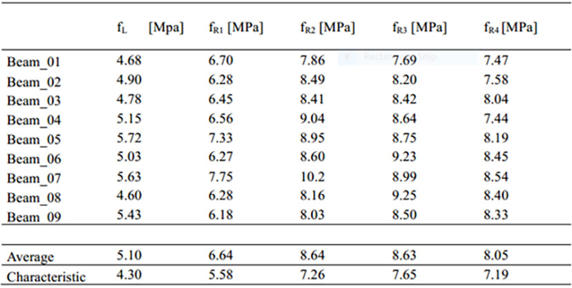
Results of beam bending tests conducted by Roma University show how a low variation provides a performance class type 5e according to Model Code 2010 (Fig 2).
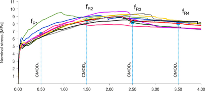
The results of such a bending test are expressed in terms of force (F) vs crack mouth opening displacement (CMOD) measured in millimetres (Fig 3).
Parameters fR,j representing the residual flexural tensile strengths are evaluated from the F-CMOD relationship according to the equation in which a simplified linear elastic behaviour is assumed:
Where:
fR,j is the residual flexural tensile strength corresponding to CMOD = CMODj
FR,j is the load measured during the test in kN
l is the span length or distance between supports = 500mm
b is the width of the beam = 150 mm
hsp is the distance between the tip of the notch and the top of the beam = 125 mm
From the above residual flexural tensile strengths, the characteristic values can be evaluated as:
fR,jk = fR,jm - k .Vx
Where:
k is the factor dependent on the number of the specimens with the recommendations for 12 beams to be tested
Vx is the standard deviation of the test results

Fig 2. Roma University beam bending test results showing how a low variation provides a performance class type 5e according to Model Code 2010
The standard deviation could be influenced by many parameters such as mix design, casting, and testing, and is also strongly influenced by the fibre number and network effect. A higher fibre network leads to a lower standard deviation, which is key to achieving the required characteristic value for design.
For the classification of the post-crack strength of FRC, a linear elastic behaviour can be assumed, by considering the characteristic residual flexural strength values that are significant for serviceability limit state (SLS) and ultimate limit state (ULS) conditions. Two parameters are especially important, and need to be specified by the designer, namely:
fR,1k : the minimum value for SLS
fR,3k : the minimum value for ULS
Materials with fR1k ranging from 4 MPa to 5 MPa are commonly used for precast segments without any bar reinforcement, combined with a fR3k/fR1k ratio in the ranges 0.9< fR3k/fR1k <1.1 or 1.1< fR3k/fR1k <1.3 which are class c or class d respectively, according to the Model Code 2010 definition.
Hardening post-crack behaviour at section level through a beam test immediately allows for crack control and for serviceability limit state design.
After many years of experience, Bekaert designed its Dramix® 4D 80/60BGP specifically for precast segments. It has a nominal tensile strength of 2,200 N/mm2, a Young’s Modulus of 200,000 N/mm2, and a strain at ultimate strength of 0.8%. Dramix® 4D 80/60BGP is supplied with a fibre length of 60mm and diameter 0.75mm, giving a length to diameter aspect ratio of 80.
Dramix® steel fibres are bundled with water-soluble glue. The glue helps avoid fibre balling during mixing and ensures a homogeneous distribution of fibres throughout the concrete. Dramix® 4D provides optimal crack control for standard statically indeterminate concrete structures that are submitted to regular static, fatigue and dynamic loadings with high serviceability. Dramix® 4D Premium is a high-performance fibre to create the optimal ductility in high-strength concrete.
In recent years, demand has increased for higher compressive strengths for the precast segment from C40 to C70. This is driven by the need for more structural requirements to address durability issues and early age demolding for increased production capacities. On the down side, the increase in concrete strength with age, and hence better bond to the fibres, leads to fibre failure in the cracks, rather than bond failure, resulting in a much more brittle behaviour.
Fibres provide a more ductile behaviour when they are gradually pulled out, and for this, hooked ends are essential to generate the ductility and post-crack strength of concrete. Bekaert Dramix® 4D steel fibres utilise this technology, which translates into improved anchorage and ductile behaviour.
A correct network effect of the fibres in the concrete is key to optimised cracking control, post-crack behaviour, fibre homogeneity and dispersion in combination with glued fibre, and low dispersion in the result.
Keeping the same network effect is essential to ensure consistent behaviour and cracking control. For example, a fibre with a length to diameter ratio aspect of 80 (60mm length x 0.75mm diameter) offers a network higher than 11km of fibre/m3 of concrete with a fibre content of 40kg/m3. A minimum network of 10km/m3 is recommended. For this a fibre length to diameter ratio of 65 (60mm length x 0.9mm diameter) will need a fibre content of about 55kg/m3. This means that using a fibre diameter of 0.9mm vs 0.75mm adds about 40% more kg/m3 to achieve the same minimum network (Table 1).
| Table 1. The parameters of two common steel fibre networks | ||||
| Length to diameter ratio |
Length (mm) |
Diameter (mm) |
Fibre/kg (mm) |
km/m3 for 40kg |
| 80 | 60 | 0.75 | 4,664 | 11.2 |
| 65 | 60 | 0.90 | 3,200 | 7.6 |
Aside from the extra cost, this additional dosage will also lead to side-effects in terms of mixing and workability.
Finally, it is worth pointing out that for FRC precast segments to be successful, work needs to be conducted at an early stage of the project on the mix design optimisation, while keeping in mind that a composite material is being developed. In addition, bending tests, such as the EN 14651 test method, have to be performed to allow the classification of the FRC according to fib bulletin 83, Model Code 2010.
Choosing the right fibre for the right performance is essential but should be done in a structured way to achieve the full benefits in terms of performance, quality and cost of the project. Dramix® 4D 80/60BGP offers a hardening post-crack behaviour in terms of crack width control and SLS design, and low variation in the result to guarantee a high-performance class according to the Model Code 2010 classification.
References
- Crack width control in FRC segments – TunnelTalk, February 2020
- Face to Face with Marc Vandewalle, a pioneer of steel fibre reinforcement – TunnelCast, May 2020
- Review of FRC brittle failure considerations – TunnelTalk, March 2015
|
|
|
|
|
Add your comment
- Thank you for taking the time to share your thoughts and comments. You share in the wider tunnelling community, so please keep your comments smart and civil. Don't attack other readers personally, and keep your language professional.


