Niagara plan of attack
Dec 2006
-
An open gripper TBM; an in-situ concrete lining; on-site construction of the largest ever, 14.4m diameter, hard rock TBM; and concurrent lining with excavation: these are just some of the alternatives Strabag AG of Austria adopted to secure the competitive edge for the Niagara Tunnel project in Canada. TunnelTalk Editor Shani Wallis Visited the project site in September to know more of Strabag's proposal, its project suppliers, and its strategy for success.
-

Fig 1. Route of the new 10.4m diameter water delivery tunnel being excavated
- The driving force behind the $Can600 million design-build contract for the 10.4 km long Niagara tunnel in Canada is early completion. Every extra day of power production through the $Can985 million upgraded and increased generating capacity of the Sir Adam Beck Hydroelectric Power complex constitutes significant operating income. To maximize the revenue, project owner Ontario Power Generation (OPG) and its project engineers Hatch Mott MacDonald and Hatch Acres, prepared contract documents that encouraged prequalifiers to present alternatives that would compress the construction period, maximize the tunnel's flow characteristics, and have the project commissioned as soon as possible. Efforts by the project's three prequalified bidders to achieve this were further concentrated by the contract's schedule of incentives based on liquidated damages of $Can250,000/day maximum for any delay beyond the contracted delivery date and a bonus of 50% of that for every day earlier. There is also a bonus or penalty for flow of water through the tunnel above or below the guaranteed 500m3/sec.
- In a truly bold move, the proposal presented by Strabag AG of Austria countered nearly every construction assumption in the bid document and presented a completely different approach that proved convincing to the client and its engineers.
-

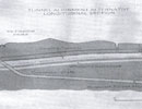
Fig 2. Niagara Falls to the inlet some 1.5km upstream of the famous Horseshoe Falls
- The defining differences of the alternative are to use an open gripper TBM instead of a shielded machine; to finish the tunnel with an in-situ concrete lining instead of a precast concrete segmental lining; to build the TBM and its backup on site rather than reassemble a shop commissioned and shipped machine; and to install the final lining concurrent with TBM excavation.
- These are daring variations. The geology as well the required diameter of the one delivery tunnel, at 14m or more, suggested that shield tunneling would be favored, The criteria for a watertight lining and for it to be completed within the incentive-driven time line suggested that a one-pass bolted, gasketed, and backfilled precast segmental lining erected within a shield would be the only way to go. As for building a TBM on site, that is a high stakes undertaking, as is solving the technical demands of installing an in-situ final lining concurrent with TBM excavation.
- In preparing its proposal, Strabag with its local sub-contractor Duffer in Construction, had to have the confidence of its major suppliers that these alternatives could be achieved. For design issues, the committed engineering partners are ILF of Austria (with an office also in Virginia, USA) and Morrison Hershfield of Toronto.
- For the equipment systems, the principal suppliers are the Robbins Company for the TBM, Rowa Tunneling Logistics of Switzerland for the trailing back-up, and Bystag of Germany for engineering of the in-situ concrete lining operations.
- A watertight finish
Engineering a watertight finish is essential to the minimum 90-year design life of the infrastructure. Some 80% of the 10.4km tunnel lies in the shale and mudstone series of the Queenston Formation that are known to exhibit swelling and squeezing behavior. These are induced by relief of relatively high in-situ horizontal stresses and the potential of the shale units to swell when in contract with freshwater. - Two drill+blast tunnels built in the 1950s to feed water to the exiting Sir Adam Beck hydro station provided valuable data for the current undertaking.
- To achieve a watertight lining, ILF proposed a pre-stressed in-situ concrete lining with a fully closed polyotefin waterproofing membrane behind. A program of contract grouting will fill any voids in the crown of the 600-700mm thick lining and provide a tight interface to the rock mass. A final program of high pressure interface grouting, injected at up to 30 bar through grout hose rings installed between the initial lining and the waterproofing membrane, will pre-stress the lining and place the entire structure under a state of compression. This will to contain the internal water pressure without the need for reinforcing steel, which eliminates the long term corrosion risk.
-

Robbins fitted the steel rib ring erector
- TBM procurement
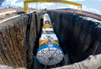
One of the longest lead-time concerns was procurement of the proposed 14.4m diameter TBM. Under a conventional machine order, with fabrication, shop assembly and testing followed by delivery to site, site assembly and commissioning , would take upwards of 15 months. A principal factor in securing the job Strabag was agreement from Robbins to build the machine on site. "This probably cost us an extra three or four weeks on a shop build, but saved three to four months in overall delivery time", said Lok Home, President of the Robbins Company. "Site construction of TBMs has been undertaken in the past, and the process does have its own set of pitfalls, but we were confident that a site build for this machine was doable." - Several points worked in favor of a site build. The TBM is an open, main beam, hard rock gripper machine and assembly of the major components is less complex than for an shielded machine. In addition many of the main components, including the drive unit, the 6.6m diameter main bearing, and the gripper assembly, are similar or identical in design to those used on the 10m rock machine supplied by Robbins to the Dillingham/Fletcher/llbau (now Strabag) JV for the second tailrace tunnel for the Manapouri Hydroscheme in New Zealand about six years ago (TunnelTalk). That was the previous largest ever hard rock TBM and Strabag's Project Manager at Niagara, Ernst Gschnitzer, was Tunnel Manager at Manapouri. He and the Strabag team know the machine characteristics and have worked with The Robbins Company in the past both at Manapouri and on other international rock TBM projects.
-

Moving platforms for immediate support work stations
- "The significant difference between the Niagara machine and the Manapouri TBM is the extra 4.4m in diameter", said Home. "That has a major influence on machine performance. Our greatest concern was to build a stiff, rigid superstructure to prevent vibration in the 14.4m diameter cutterhead and ensure constant and uniform contact of the discs to the rock face. The rock Formations at Niagara are not especially hard, ranging in compressive strength from 19 to about 45MPa for the majority of the drive through the Queenston shale and mudstone, and up to 150MPa through the upper limestone layers, but any sustained vibration of the big, flat rotating cutterhead will over stress its structure, interfere with uniform penetration and in turn cause tool breakages, excessive wear and reduced advance."
- Along with its other record setting statistics, the Robbins machine will be the first to use the Company's new 20in (508mm) cutters. "Although only one inch larger in diameter than 19in cutters, these 20in cutters have significant benefits", said Home. "They weigh about 3% more than a 19in disc but have 35-40% more ring wear volume which increases cutter life significantly. This reduces the number of changes needed and in turn increases TBM availability."
- With a cutter spacing of 89mm, the 14.4m diameter cutterhead is dressed with 85 x 20in cutters. Robbins has a cutter consumption contract with Strabag for the Project.
- A core team of eight Robbins technicians were on site during the four-and-a-half months it took to build the shop manufactured and tested components of the machine. In what was described as an unprecedented achievement for a machine of its size, the TBM was ready for an official cutterhead turning ceremony on 8 August, some three weeks ahead of the penalty-driven 1st September contracted start-boring due date.
- Trailing Backup
Behind the TBM are the four trailing elements of the systems's 105m long logistics backup. Designed, manufactured and assembled on site by Rowa Tunneling Logistics, the first of the four elements is supported on hydraulic legs while the remaining three are towed on rollers running directly on the tunnel invert. -

Crane System that is fixed to the tunnel's crown
- As well as all the necessary workstations, workshops, power support installations, storage areas, and ancillary equipment, the back-up provides the platform from which the immediate support elements are installed. These comprise mainly rockbolts of up to 6m long, steel sets where needed, wire mesh, and layers of shotcrete.
- "The principal requirement of this installation was to prevent any backup caused delays of TBM production", said Jost Wenk, Managing Director of Rowa. "This demanded efficient movement of supplies and materials and required a certain independence of movement between TBM advance and immediate support application stations."
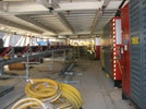
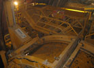
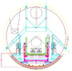
- To streamline management of materials, Rowa installed several crane systems through the four working levels (including the tunnel invert) of the 14.4m tall structure.
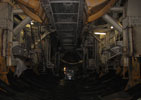
- The most innovative of these is a mono-rail crane system that is attached to the crown of the tunnel. Operating completely independently of the backup, the system provides a full length uninterrupted supply line of materials from the trailing gantries to directly behind the cutterhead. Rail sections are moved forward from the back as the machine advances.
- "This suspended gantry crane guarantees smooth operations", said Wenk. "It allows materials needed for tunneling to be put to use immediately behind the cutterhead without any interim storage. With a swivel and telescopic boom on the crane, this is a highly mechanized delivery system, which is a further trump card in the tough battle for performance and cost efficiency."
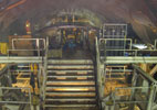
- On the backup there are two immediate support platforms both of which can move independently of the TBM.
-

Rowa designed the four-story backup
- The first is located directly behind the cutterhead. From here full ring sets, or partial arch channels held by 2.4m rockbolts, can be installed, wire mesh can be placed and layers of shotcrete can also be applied if necessary. These immediate support elements are expected to be need in particular at the start, and at the end, of the drive where the steep tunnel gradient cuts obliquely through the horizontal layers of the upper strata (Fig 2). The alignment is governed by the need to pass beneath a deep buried gorge at the start of the drive at the tunnel's outlet portal.
- Shotcrete is used throughout the drive as an element of support and as a method of sealing sensitive rock types against the degrading affects of contact with water and air. Two newly developed shotcrete robots, one for each primary support work station, provide all-round 360° shotcreting of the 14.4m diameter tunnel. They can travel through a longitudinal displacement of 8 m for the forward installation and through 20m for the main shotcreting station. Each of the two moving stations is also equipped with two independent drill rigs for installing rock bolts of up to 6m long.
-
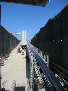
The H+E continuous conveyor carries spoil up the access ramp
- From the second working station, all elements of primary lining are installed within 40m of the face. The longitudinal displacement of the working decks and the full round shotcreting robots is designed so that the heaviest class of prescribed immediate support can be applied without holding up TBM advance.
- In addition to the immediate support systems, Rowa also supplied other items of equipment on the backup including grout pumping equipment, compressed air installations, industrial and cooling water plants, dedusting equipment, ventilation duct storage, and transfer conveyor.
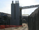
- In providing the backup system, Rowa worked with Robbins on the interface with the TBM and with H+E Logistics of Germany who supplied and installed the contract's continuous conveyor muck hauling system. From the Robbins TBM transfer conveyor, muck hauling system. From the Robbins TBM transfer conveyor, muck travels on the Rowa feeder conveyor through the backup and onto the H+E shoulder-suspended continuous conveyor. At the Tunnel portal the H+E conveyor rises up the access ramp, past the site's concrete and shotcrete batching plant (where more than 400,000 tonne of concrete will be batched for the project) for relay to a transfer conveyor that carries material to the muck storage site.
- Through its operating time, the conveyor system will haul more than 1.6 million m3 of rock from the 10.4 km long x 14.4m diameter tunnel. On the alignment, the conveyor will negotiate the steep inclines at either end of the drive and a minimum 600m radius horizontal curve.
- Transport to and from the TBM will be via a fleet of rubber tired vechicles supplied by Plan and Techo of Germany. The ventilation system is supplied by Cogemacoustic of France and includes one ventilation fan stationed at the tunnel portal, 10.4km of 2.6m diameter flexi ventilation ducting and one booster fan to be introduced as the tunnel lengthens.
-

Past the concrete batch plant, through a relay station
- Concurrent concreting
Perhaps the most technically demanding aspect of Strabag's alternative is proposed casting of the full in-situ concrete lining with its PVC waterproffing membrane concurrent with TBM advance. The challenges of making this work logistically have been taken up by the team at Bystag in Germany. - "Both the invert and the arch lining will progress concurrent with excavation", said Kurt Usel, owner and managing director of Bystag.
- "The invert will progress first, starting about 400m behind the TBM. About 400m behind that, the arch concreting is planned to follow. Each concreting installation will have two 12.5m long forms that will cast in leap-frog sequence to provide 25m of lined tunnel/day. That is the plan."
- Designing concrete casting systems for a 14.4m diameter circular tunnel that will at the same time keep all excavation services and supplies operating without interruption is a tall order. For the invert, the shutters are incorporated into an 87m long bridge with a ramp each end for a total 87.5m that will allow rubber-tired TBM supply vechicles to travel over the cast invert and the rock floor of the tunnel.
-

Onto a transfer conveyor to the muck storage site
- The forms will cast the invert lining to just below spring line. To prevent up-lift, the two 12.5m long forms on the bridge will be braced against the tunnel crown and via hydraulic braces against the tunnel wall at just below. The single traffic lane for the transport vehicles through the bridge structure is between these braces, the crown vent duct hangs from the centre line between the crown braces and the conveyor remains on its initial shoulder brackets
- "For the arch forms, things get more tricky", said Usel. "The transport vehicles are now traveling through the forms on the concrete invert but both the vent duct and the continous conveyor have to come off the tunnel walls onto diversions through the forms and be transferrred back onto the new concrete lined walls at the back end."
- As part of both the invert and arch casting processes, the PVC waterproofing system and the grouting rings for pre-stressing the lining have also to be installed. "Integrating all activities on a smooth running rolling program and establishing familier rounties for the crews will be key to maintaining optimum production", said Usel.
|
Eyes on the alternative The implications of the Nigara approach for compressing tunnel comstruction times by allowing contractors, with consultants and system suppliers, the space to innvote, may provide the springboard needed to elevate tunneling to an unavoidable necessity. Following the Niagara experience, Robbins has adopted on-site build of two 10m gripper TBMs to fill a $135 million order for a large water diversion project in India, an order that includes the trailing backups and the continous conveyor system for each machine set. Foe Rawa, Wenk said that "the improvement of the interfaces and the reducation of the transloading sites are the deciding success factors." For Bystag the Niagara order adds to a list of innovative solutions it has offeres since its busines start up in 2000. For Strabag the prize is ahead Within its 51-month design-build turnkey contract to December 2009, excavation of the 10.4km long tunel is programmed to take 23 months starting on 1, septenber 2006. Concurrent Casting of the final lining programs it too to finish not long after TBM breakthrough. |
||||||||||||||||||||||||||||||||||||||||||
- In late November, the complex tunneling system was into the tunnel drive but still had a ways to go to reach optimum performance. Once all systems are syvchronised, debugged and running smoothly, it will be all systems go for the 24/7 tunneling crews. With the invert concrete lining system scheduled to launch in about February, the full tunel production line will be heading towards an excavation breakthrough in about September 2008.
Gallery
|
|
|
|
|
Add your comment
- Thank you for taking the time to share your thoughts and comments. You share in the wider tunnelling community, so please keep your comments smart and civil. Don't attack other readers personally, and keep your language professional.


