Sinking the concrete elements at Midtown 3 Dec 2014
Three of the 11 elements are now secured in place on the bottom of the Elizabeth River as construction of the Midtown immersed tube link between Portsmouth and Norfolk continues to make good progress towards a 2018 project completion date.
TunnelTalk reporting
Immersion of the eleventh and final concrete element completes for the first time a connection between the Norfolk and Portsmouth sides of the Elizabeth River in Virginia, USA.
Completion of the sinking operation on Tuesday (14 July) comes nine months after the first element was laid in October last year (2014). Project Director Wade Watson said: “There is still a lot more to do, so I am not totally comfortable but this brings to the end a big portion of the job.”
The new immersed crossing will, once completed, provide relief for the existing two-lane Midtown tunnel by moving westbound traffic into the new infrastructure and enabling the existing tunnel to become eastbound only – effectively doubling capacity.
Work now starts on laying the road deck and installing a sprinkler fire safety system and other M&E installations.
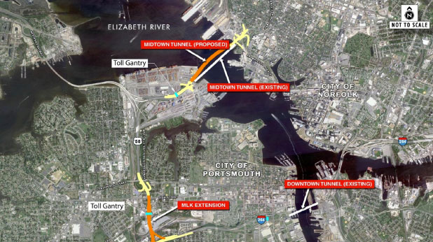
Awarded in 2011 as a 58-year PPP concession to a private consortium led by Skanska Infrastructure Development and Macquarie Group, and with Skanska USA Civil, Kiewit Construction and Weeks Marine engaged as design-build contractors, the 1,700m-long curvilinear immersed tube crossing forms the major part of a wider project that also includes rehabilitation of the existing Midtown and Downtown tunnels, and an extension of the Martin Luther King (MLK) Freeway.
The new Parsons Brinckerhoff-designed two-lane Midtown Tunnel, which is being constructed broadly parallel to the existing bidirectional Midtown Tunnel, features a curvilinear path to take it a safe construction distance away from the original immersed tube. It is believed to be only the second immersed link in the USA to feature the rectangular concrete element design profile that is more commonly seen in Europe. The more usual preference in the USA since the use of immersed tunnels became more commonplace in the 1960s, has been for a steel or cast iron tube construction.
The first six concrete elements for the Midtown Tunnel, manufactured in dry dock some 200 miles away from the project site at the docking facility at Sparrows Point, Baltimore, began arriving by tug boat in June (2014). Construction of the remaining five elements can now take place and these are due to be tugged to the project site later in 2015. Each of the elements is tugged down Chesapeake Bay and then out into the waters beyond the Chesapeake Bay Bridge-Tunnel.
This potentially hazardous foray into open ocean towards the end of the journey is necessary in order to navigate water deep enough to turn through 180 degrees and make the deeper waters of the Norfolk side of the bay. Each element takes 4-7 days to complete the journey (Fig 1). “Going out into the ocean presented a potential problem with waves, and with the timing of the 180 degree turning operation, but as it happened, for this time of year the conditions were perfect and we managed to get all six elements transported and moored up by July 3 – which was just 24 hours before Hurricane Arthur passed by,” Elizabeth River Crossings construction director, Dallas Marlow told TunnelTalk.
“We knew it was coming but we got the timing perfect. We got the last unit down and tied off at Portsmouth Dock, which itself had to be strengthened to take hurricane loads.”
The whole operation, explained Marlow, was a carefully calculated risk. The construction team knew that a hurricane was forming, he said, but the opportunity that was presented by “perfect” conditions for the time of year in the days leading up to it made the choice irrestistable. “We had a fall back plan that would have involved taking shelter in Cheseapeake Bay with the last element had it been necessary,” said Marlow.
Construction of the elements is made more complex by the need to accommodate connections on different vertical and horizontal planes as the tube navigates the open-U-shaped trench dredged into the river bed, as well as the curve that takes it away from its 1960s-built sister tunnel.
Additionally, not all elements are the same length, with those in the centre section of the alignment (Elements 5-7) somewhat shorter than the rest. “We are on a vertical curve as well as a horizontal curve so every bulkhead is constructed differently to accommodate this shaping,” explained Marlow.
The bulkheads on the first four elements are constructed to enable a vertical gradient from the Portsmouth side of-4.4%; Elements 5 and 6, -0.5%; Element 7, +0.5%; with the bulkheads of Elements 8-11 enabling a rising +4.5% alignment back up to the final shoreline connection with the cutoff wall and bulkhead that are incorporated into the cofferdam at the far end of the cut-and-cover section on the Norfolk side of the river (Fig 2).
A similar cofferdam endwall and bulkhead configuration is constructed also on the Portsmouth side, from where laying of the elements has begun. “The final roadway slab will take out any discrepancies that we have to form a smooth vertical curve inside the elements,” Marlow told TunnelTalk from the USA.
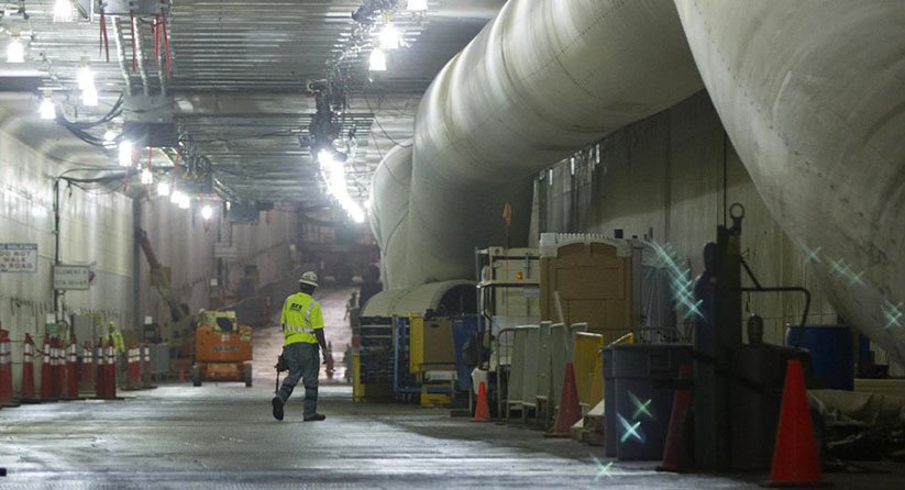
Additionally, the bulkheads on the elements have to be constructed to facilitate an out-to-in horizontal curvature across the whole alignment of 75-80ft (Fig 3). “We had to make sure that we were far enough away at mid-river so that we didn’t undermine the existing tunnel, especially during dredging,” said Marlow. To give as much warning as possible of any movement of the existing steel tube, monitoring stations were installed a year ahead of construction start in 2012, during which time baseline movement figures were established. “Any movement detected would have sounded an alarm and informed any of a dozen people, although in the event, two years into construction there has been no movement detected,” said Marlow.
After arriving at the Elizabeth River project site each element is moored at the Port of Virginia on the Portsmouth side, in advance of a sinking operation which began in early October (2014). The second element was laid early last month (November 2014) with the third and most recent sinking operation taking place in just the last few days.
Sinking and completing the final underwater alignment and connection of each section takes up to 18 hours after being floated from their moorings in the Port of Virginia, and into position. The last three of the first batch of six elements that were moored in June and July (2014) are expected to be maneuvered into place at the rate of approximately one every five weeks between now and February 2015. Each element, weighing 16,000 tonne and with a cross sectional profile measuring 46ft wide x 33ft high, is maneuvered by lay barges into position above its final resting place on the previously dredged and screeded river bed.
At their deepest elevation, the elements under the center of the river and below the Federal Shipping Channel, will sit under 95ft of water. The depth of water above the first and eleventh elements will be barely 10ft near to where they join with the concrete bulkheads of the cut-and cover approaches at either shore.
Fixing the 10th and 11th elements next year (2015) will require a complex jigsaw-type operation to lock in the final connection between Element 11 and the cut-and-cover bulkhead on the Norfolk side. “Tunnel elements draft 26ft when they are floated into place but Element 10 only has 16 feet of clearance on the high side or upslope end,” explained Marlow. “Element 11 will therefore be floated into place [but not lowered] before Element 10 is moved into position. Element 10 will then be floated into place and lowered into Element 9, and only then will Element 11 be lowered from its floating position and joined to Element 10. The cofferdam will then be resealed and a closure pour carried out to connect Element 11 to the Norfolk side cut-and-cover.”
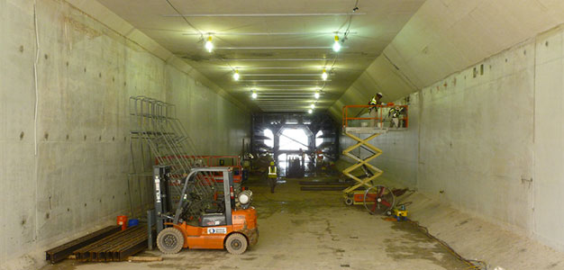
On the Portsmouth side the cut-and-cover approach tunnel to the cofferdam endwall and bulkhead measures 225ft long, while on the Norfolk side it is slightly longer at 280ft. Both sides of the connection also feature open cut approaches of 670ft and 580ft into their respective cut-and-cover sections. Once construction of the new tunnel is completed, and following rehabilitation of the broadly parallel 1960s-built Midtown immersed tube, traffic will become 2-lane unidirectional, with the new tunnel serving eastbound traffic and the old one westbound traffic. It is expected that the new tunnel will save drivers an average of 30 minutes traveling time, and significantly reduce queues that can reach as long as two miles on the portal approaches.
Once the elements are lay-barged into place, getting the negative buoyancy right is critical to the successful sinking operation, explained Marlow. “As we get them into place weight is slowly added either by adding concrete blocks on the roof or by increasing weight inside the ballast chambers inside the unit – this process continues until we have 2% buoyancy and then we set it down on the bottom, about a foot from the marrying-up position. Once we are sure the slope is all correct we can begin making the sealed connection.”
This connection is made using the standard hydraulic pressure method. A hydraulic ram fixed to the previously layed element pulls the new one tight against it and a connection between them is made using the Gina gasket and Omega sealing system (Fig 4). As the temporary bulkheads between the two elements are pumped dry of water the pressure from the leading bulkhead engages and compresses the sealing membrane, locking the two elements together for a watertight connection.
Following completion of the sinking and coupling operation, initial backfilling begins to secure the position of the element in its dredged trench on the river bed. Once all elements are in place the trench will be filled with 550,000 yd2 of ordinary fill to just above roof level using the clam and bucket method from above. A further 23,000 tonne of anchor bands and 39,000 tonne of armour stone will then be laid over the top surface of the tunnel elements.
With the completed tunnel at risk of inundation on the lower lying Norfolk side as a result of frequent tidal surges during the hurricane season, the design includes improved drainage around the entrance and construction of a protective levee. “We recorded a tidal surge of 7.1ft during Hurricane Sandy in 2012 that inundated the entrance to the existing tunnel, but with the new design we can withstand tidal surges of 10.25ft,” said Marlow. “The existing tunnel has flooded twice in its history so even before Hurricane Sandy it was determined at design stage that we needed to raise the capability for withstanding inundation.”
A final element of the contract is the rehabilitation of the two Downtown tunnels and the old Midtown tunnel. If this work were to be stripped out of the main US$1.46 billion contract, it would be valued at approximately US$100 million, according to Marlow.
Work cannot start on the Midtown rehabilitation until completion of the new immersed tube, but is well under way in the Downtown tunnels. Most of the upgrades are aimed at improving fire-life safety, with ventilation installations being upgraded from their current 20MW rating to 100MW. Ventilation on the Midtown tunnel will also improve naturally once it becomes unidirectional, with the one-way flow of traffic invoking the “plunger effect.” Improvements are also being made to the lighting inside the tunnels to increase luminosity from 3.8 lumens to nearly 30. “The difference is remarkable,” said Marlow.
As construction progresses Tunneltalk will update this project report.
Gallery
References
- Tidal gates save Midtown Tunnel from floods – TunnelTalk, November 2012
- Financial close seals Midtown Tunnel start – TunnelTalk, April 2012
- Midtown P3 contract awarded in Virginia – TunnelTalk, December 2011
- Citybanan starts complex sinking operation – TunnelTalk, May 2013
- Reflecting on Europe’s first immersed tunnel – TunnelTalk, March 2013
- Submerged floating tunnels and links across the waters – TunnelTalk, January 2010
|
|
|
|
|
Add your comment
- Thank you for taking the time to share your thoughts and comments. You share in the wider tunnelling community, so please keep your comments smart and civil. Don't attack other readers personally, and keep your language professional.


