Mountain drives for water supply in Malaysia
Apr 2012
Shani Wallis, TunnelTalk
-
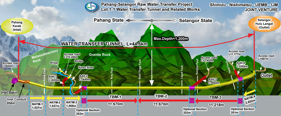
Fig 1. Cross section of the long water delivery tunnel and its points of attack
- Long TBM headings of more than 11km each, plus an additional 9km of NATM excavation, combine to form one of the world's longest tunnels. The 44.6km Pahang-Selangor raw water delivery tunnel in Malaysia is more than 50% complete (to mid-April 2012) and about 3% ahead of schedule towards the end goal of increasing water supply to the country’s capital city, Kuala Lumpur.
- Work on the project started in mid-2009 when a ¥38 billion (about US$465 million) contract was awarded to a joint venture of Shimizu and Nishimatsu of Japan (30% each), with local partners UEMB and IJM (20% each), to excavate the long, 5m diameter tunnel through the mountains from Karak in Pahang State to Langat, near Kuala Lumpur, in Selangor State (Fig 1).
-

Three 5.2m diameter High Performance TBMs are completing the longest headings under the highest overburden
- With the overburden of dense tropical jungle rising to more than 1,200m above the alignment, locations for access adits were limited. To progress excavation, and have the tunnel completed within the 60-month contract period, the JV elected to use three new High Performance 5.23m diameter main beam gripper TBMs from Robbins for the longest reaches beneath the highest overburden, and conventional NATM through sections of lower cover at the portals where geological conditions were predicted to be less TBM favourable.
- "The longest heading is 23km with no intermediate adit or access," explained Deputy Project Manager of the JV, Yoshikuni Nakano, of Nishimatsu. "We have two TBMs working towards each other on this critical path element and breakthrough is currently estimated for about May 2013."
-
TBM programme
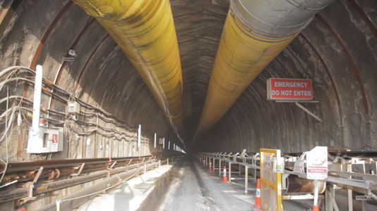
The long tunnel is divided into seven faces, three long TBM drives of 11.77km, 11.80km and 11.30km, from Adits 4, 3, and 2 respectively, plus four NATM headings, one in each direction from Adit 1 upstream, another from the inlet to Adit 1, and the fourth from the outlet portal to Adit 4 downstream (Fig 1). - When TunnelTalk visited the project in March (2012), the TBMs were about 6km, 4km and 4km each into their respective drives with TBM2 making best headway. Working from Adit 4 through softer, more fractured granite of about 120MPa UCS, rates of up to 40m/day, of two 12hr shifts per day with a maintenance schedule of as long as needed during the first shift per day, were being logged. Latest reports from the site confirm that this TBM has now passed the 7.2km mark, and is projected to be the first to complete its drive in about October 2012.
- The other two TBMs were having a tougher time. TBM1, heading on a gentle down hill gradient of 1.9‰ from Adit 2, was at a standstill during the visit, held up by a fault zone of loose crumbling rock that was falling away to create a large void above the 5.2m diameter cutterhead.
-

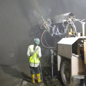
Drilling pre-excavation injection holes into a void fault zone
- "Crews are having to stabilise the zone with forward consolidation grouting," explained Andy Birch of Robbins and Site Manager of a team of six Robbins Field Technicians engaged full time on the project by the JV - an electrician and a mechanic at each TBM site. "Once the area is secure, the TBM can advance into stable rock on the other side and be away again."
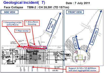
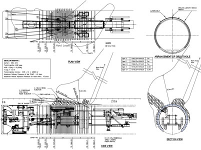
- This was not the first geological anomaly encountered, or the largest. "Not all the problem areas encountered have been fault zones exactly," explained Frank Pittard, lead geologist with the construction JV. "Some have been areas of loose, closely-jointed rock with ground water and there have been fault zones with gouge. The most difficult section to date was in the TBM2 drive, about 1.5km from Adit 3, where one fault zone proved particularly extensive. More than 400m of difficult rock conditions were encountered. It included zones of gouge and hard rock and had also a large cavity that extended at least 50m above the alignment. The TBM did not excavate an excessive amount of material from this zone to create such a large void. It appears to have been a pre-existing feature. Pre-excavation grouting was carried out for a 12m reach and post-excavation back-grouting was carried out in a number of areas."
- During the March visit, with the TBM, at that time, more than seven months and 500m beyond the July 2011 incident, a more permanent backfill of the void had yet to be applied. Design of an appropriate final lining (on the otherwise unlined tunnel) was also yet to be finalised. Latest news from the project in early April, confirms that crews are carrying out additional drilling works for back grouting the void. The works are being carried out from a purpose-built gantry that allows the TBM service trains to continue operations without interruption.
- A stop at the zone on the way out from visiting TBM2 witnessed a wet area where ground water had found its way into the excavated space, and an information board on the wall detailing the anomaly and the temporary support works applied.
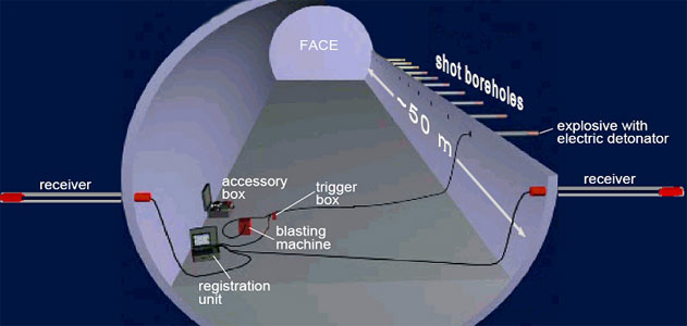
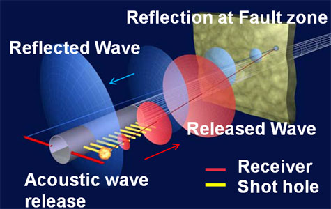
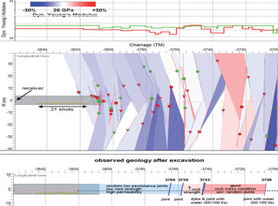
- Knowing the high probability of meeting fault zones on the long mountain drives, the JV is applying TSP (tunnel seismic prediction) systems. Lateral 'shot' holes are drilled into the tunnel's side walls to send acoustic wave signals into the rock ahead of the face. Drill holes behind the shot holes receive waves reflected back from any fault zone, fissure or anomaly. The JV reports mixed results of the application of the technology that will be explored in a coming technical article on TunnelTalk.
- Ironically, it was the same TBM2 from Adit 3 that was having the hardest time of the three machines and through the best quality rock. Massive granite of up to 200MPa UCS, with no visible jointing and a 30% quartz content, had TBM penetration rates down to less than 1mm/cutterhead revolution and wear of the 19in cutters higher than anticipated.
- "The rock is so hard and massive that the TBM is grinding the face rather than cutting chips," explained Birch. "This has slowed us down dramatically. It is taking up to two hours to cut a 1.5m stroke. The hardness and massiveness of the rock is also requiring high thrust forces, of up to 10,000kN, which is near the maximum recommended thrust and approaches the maximum load/cutter of 312kN for the 27 x 19in face cutters and 8 x 17in centre cutters on each 5.2m diameter cutterhead. These high forces stress the cutter housings and a coming scheduled stop for installing rail switches will give us the opportunity to strengthen, in particular, the centre cutter housings."
- Yet at these thrust forces, the TBMs are operating below their total High Performance capacity. "The TBMs are very powerful," said Deputy Project Manager Nakano. "Working at 10-11,000kN through rock of +200MPa UCS, they are using about 75% of the full 14,000kN thrust capacity. The operators' cabin also has a very high specification. Each is linked, in live time, to the site office on the surface as well as to the project head office and, via the internet, to the Shimizu and Nishimatsu headquarters in Japan. We have 24-hour Robbins support on the machine and the Robbins technicians have helped train our operators and TBM crews. This has been undertaken outside the terms of the Robbins contract, which is very friendly and helpful."
|
|
||||||||||||||||||||
- "Back-loading is a weak point," was his opinion. "The housings need to be stronger for back-loading, highest-thrust performance." Compromising the safety benefits of back-loading cutterheads for marginal front-loading advantages would be hard to justify.
- As well as ever-higher hard rock performance, the desire of contractors for ever-more durable cutters also continues. Robbins and the JV are sharing the cutter consumption contract and have been working together to increase penetration rates and optimise cutter consumption. Quartz content at 30% is not more than estimated, but cutter consumption was higher than contract assumptions during the visit. The 312kNm/cutter bearing capacity for the 19in face cutters is being exceeded on occasions in very hard rock and changes of the worn gauge cutters are needed after boring about 7m-8m linear metres of tunnel. To maximize penetration rates and reduce downtime for cutter changes, Robbins has provided different types of disc rings. Various tip widths and ring heat-treatment processes have been tried and performance has been monitored in order to identify the best configuration.
- Several other factors however, influence the application of maximum power to achieve optimum progress. As Birch explained: "The stated minimum excavation rate of 3mm/min is in rock strengths of more than 200 MPa. This is attained with the maximum thrust of 10,900kN force at 11 rev/min. If this force is exceeded it impacts the life of the machines' main bearings and the structure of the TBMs. There are also so many other issues that influence progress. There is a shutdown for example almost every afternoon due to severe thunderstorms in this tropical region. These cause major problems on the electrical systems. In the early days, we worked through these storms and burned out several plc control cards. Replacing these caused more delay than the shutdown to allow the storm to pass. The TBMs are operating 24hr/day, 7 days/week with about 2-5hr/day for changing 4 to 8-9 cutters and to complete other TBM maintenance tasks, but these other causes of interruption should be included in the overall progress calculation. Often they are not."
- "At present we are achieving a consistent average of about 400-450m/month," continued Birch, "and our best to date is 721m/month. This could improve with improvements in the logistical backup and support systems and 1,000m/month is the goal, although as the headings get longer, the target will become harder to achieve. We have completed about 14km or 45% of the TBM drives in a total of 29 machine-operating months (to March 2012). Combined progress is ahead of schedule at the moment and maintaining the current 400-450m/month average/TBM to the end, the machines will have completed 34.4km of 5.2m diameter hard rock TBM tunnelling in an anticipated total of about 80 machine-operating months. Without tempting fate, this would be a significant achievement."
-
Robbins TBM supply
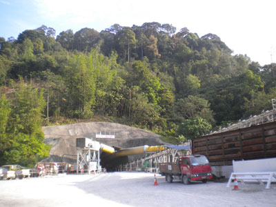
All three TBMs are identical in design and were manufactured at the Robbins factories in China, in Shanghai and Jui Ba. Each 5.2m diameter machine took about three months to build, assemble and factory test for the JV's acceptance before the first was delivered to site three months early in August 2010. The second followed in November 2010 and the third in mid-December to January 2011. - Ahead of TBM arrival, the JV was busy preparing for their arrival and launch. Local partners for example had the task of building 16km of new access roads to the remote job sites and a further 2.5km of steep 6-10% down gradient drill+blast access adit and starter tunnel excavations (Fig 1). With drill+blast able to mobilise quickly after award of contract, excavation of the adits was always ahead of schedule and ready to take delivery of the TBMs up to three months earlier than scheduled. Each TBM was assembled on the surface and walked down the adits into the headings. The first away was TBM3 from Adit 4 in November 2010. Next, TBM1 launched at Adit 2 in January 2011, and TBM2 started from Adit 3 in February 2012.
-
TBM support and logistics
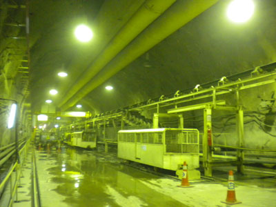
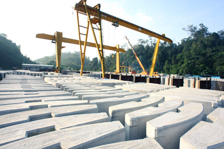
Behind the TBMs, muck haulage is via continuous conveyors supplied to the project and installed also by Robbins. The 914mm wide belts have a hauling capacity of 895m3/hr, transferring the material through the steep adits to surface stockpiles. Much of the good quality rock is recycled into the precast concrete invert segments of the TBM drives, and off which the TBMs can apply forward thrust if necessary, and into the in-situ concrete lining of the NATM sections to the 5m i.d. circular profile.
-

Low pressure mortar shotcrete support application
- For the most part, the tunnel alignment runs through competent rock that requires minimal support. Despite the limited number of site investigation cores, geological conditions are much as predicted with shale and schist under the shallower cover of the NATM headings, and softer Karak limestone formation for TBM3 from Adit 4, and hard granite for the central 23km drives of TBMs 1 and 2 from Adits 2 and 3. The amount of very hard, massive granite however is more than predicted.
- "The granite is rock class B, which requires minimal support," said geologist Pittard. "The worst rock is class E and this we have encountered in the fault zones. Rockbolts of different patterns are required in classes CI and CII and there are steel ribs and consolidation grouting needed in class D."
- There are two rock drills mounted on the TBMs behind the cutterhead for rock bolting and probe and pre-excavation grout hole drilling but these are used mostly in the fault zones. Probing is only required ahead of identified fault zones and pre-excavation grouting has been used only sparingly and also in fault zones encountered. A ring beam erector was provided with the TBMs but it was found that erecting the 100mm ribs was easier by hand.
- Rock bursting under the high cover was not, and is not, expected to be a major concern, with the maximum and minimum stresses, running parallel with the tunnel, being not too intense. The prediction of squeezing conditions in the fault zones is also proving less severe than expected. Water from hot springs of up to 37°C however has been encountered.
-
Low-pressure sprayed mortar support
For all three TBM drives, the JV is applying a systematic primary layer of fibre mortar shotcrete, a special type of sprayed lining developed in Japan. Completely different to normal shotcrete techniques, it is a very wet mix of sand and cement (no aggregate) that is applied using low pressure. The secret of the system is a high dose of liquid accelerator added to the dry mix with water at the hand-held nozzle with polyfibre also added to the mix.
-

High specification TBM operators' cabin
- The quick set provided by the accelerator allows the material to be applied to even a wet rock face and one with flowing water. It is applied in the L1 section of the TBM, very close behind the cutterhead. It is sprayed to a thickness of 200mm at a maximum pressure of 1.5 bar and in one pass across the 180º arc of the crown. During a mortar shotcreting cycle, a second crewmember can wash down the TBM as the material is being applied, the added water evidently having no affect on the success of the mortar to stay on the wall.
-
The advantages of the system are many and include:
• much reduced rebound, which reduces waste and makes for easier clean-up and housekeeping on the TBM;
• much less dust, which is a major bonus in the confines of the TBM heading;
• it can be applied during TBM excavation; and
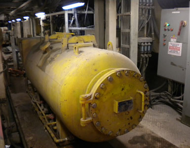
• the end product has a compressive strength of up to 15MPa within 24hr, which is a durable final lining in the non-pressurised water supply tunnel. - The dry mortar mix with the polyfibre is transported into the headings in pressurized units that are lifted off the flatcars and onto the TBM backup. Release of the pressure within the units provides the force to transport the material along the hose and spray it against the wall.
- The method has been used in Japan on numerous TBM and NATM projects but this is believed to be the first use of the technique internationally. It is sure to find wider application as news of the benefits of the technique spread.
-
NATM headings
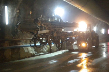
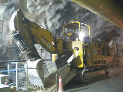
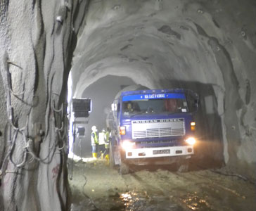
The total 11.6km of 5.2m wide x 5.2m high NATM excavation is excavated using four 2-boom+basket Atlas Copco Rocket Boomers with 170kg class drifters with four ITC-Schaeff loaders mucking out into a fleet of 15 Volve 10T dump trucks. Support is via different patterns of rock dowels, to suit different rock classes, and conventional wet-mix shotcrete applied by four Sika-PM407-P shotcreting robots with a spraying capacity of 20m3/hr.
- The straight wall, inverted U profile of the NATM headings was said to be selected to maximise the area of the headings and limit the volume of excavation and concrete lining. "A rounded profile would increase excavation and the thickness of the concrete lining to the required 5m finished diameter," explained, Site Engineer Zulkarnain at Adit 4 for the owner's consulting engineer, a joint venture of TEPSCO (the Tokyo Electricity Company engineering department), SMEC of Australia and SMHB of Malaysia.
- Engineer Zul further explained that geological conditions encountered were mostly rock class C1 that requires 100mm thickness of wire mesh reinforced shotcrete and a pattern of nine 2m long rockbolts on 500mm centres around the full profile.
- When TunnelTalk visited the site, the three upstream NATM headings, from the intake portal and in either direction from Adit 1, were complete and the 12m long concreting formwork was installed and had just started casting the final lining from Adit 2 working backwards from the TBM1 adit. The fourth 2.8km long NATM heading from the outlet portal was progressing well and towards a breakthrough into the Adit 4 TBM working chamber in July.
-
Project scope and design
When complete, the long tunnel project is designed to convey water at a volume of 1.89 million m3/day from the planned reservoir to the outlet treatment works before onward distribution to urban consumers of Kuala Lumpur. The project is being built by the Malaysian Ministry of Energy, Green Technology, and Water and is supported with 75% funding from the Japanese Bank of International Cooperation (JBIC). The tunnel is one of four project contracts, the others comprising two intake and pumping station contracts at the upstream end, which are both let and advancing, and Lot 1-2, for construction of the proposed Kelau Dam to create the project reservoir in Pahang State. Downstream the overall project includes a proposed treatment plant and connections to existing and new distribution works.
-

NATM final lining operation
- The project has attracted some controversy in Malaysia with some local politicians in upstream Pahang State objecting to long-term diversion of water from the State and to the compensation packages awarded to State residents who have had land expropriated for the project. Nonetheless, the project is moving forward and new agreements are being negotiated with the two project States.
- In the meantime, the three TBMs continue their journey to finish the long 44.6km delivery pipeline through the mountains. The last report from the project in early April has the TBM3 heading from Adit 2 now more than 7.1km into its 11km drive and both TBMs 1 and 2 more than 4km into their long headings.
- "Excavation is progressing well," said Birch. "We are through the learning curve and progress is reaching 140-155m/week. The operators have gained considerable skill in getting the best of the TBMs in these hard rock conditions and cutter consumption has improved drastically. The rock is still hard, but not as hard and massive as the +200MPa of six weeks ago, and is more fractured which is reducing the demand on all the TBM functions. We are more than half way through the job now and into a routine that has the last breakthrough scheduled for about May 2013."
- Malaysian raw water tunnel awarded - TunnelTalk, May 2009
Predicting rock conditions ahead of the face - TunnelTech, September 2012
Robbins trio to team up in Malaysia - TunnelTalk, November 2009
Robbins launch on Malaysia's mega water project - TunnelTalk, February 2011
|
|
|
|
|
Add your comment
- Thank you for taking the time to share your thoughts and comments. You share in the wider tunnelling community, so please keep your comments smart and civil. Don't attack other readers personally, and keep your language professional.

