Mumbai Metro NATM station excavation 12 Mar 2020
Kalbadevi Station is located in the heart of the densely inhabited heritage district of Mumbai with old buildings on surface. To cope with the challenges, the design approach for creating the station focuses primarily on minimising disturbances to the surroundings. The station is being constructed as a mined station using NATM with temporary cut-and-cover access boxes at both ends.
The geology for the area is mostly Class-II and I basalt rock with high compressive strength and rarely fractured. The approach adopted includes removal of the earlier TBM drive segmental linings followed by widening of the platform tunnels and construction of three 6.7m adits to connect the platform tunnels to the central concourse cavern using drill+blast excavation (Fig 1).
Excavation began with advance of the running tunnel TBMs through the station zone. The TBMs launched from the CST Station and one of the TBMs completed its drives at Mumbai Central Station in August 2019. The parallel TBM is expected to break through at Mumbai Central in March 2020. The sacrificial segments of the segmental linings are the same quality and design as the segments of the permanent running tunnels. Approximately 1,200 segments in a total 304 x 1.4m wide rings of segmental lining will be demolished to create the 211m long station platform tunnels.
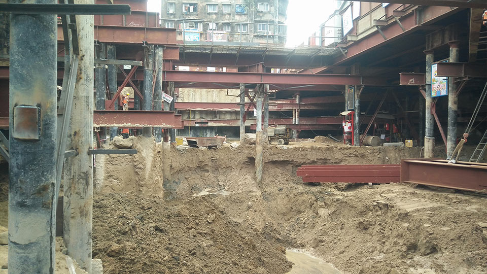
Onto the tunnels will be constructed two 27.5m deep cut-and-cover shafts to base slab level using secant piles to support the excavation. In the densely populated area Kalbadevi Station, the identified location of the shafts requires some buildings to be demolished and the residents and businesses relocated. In addition to the urban density, other challenges include stringent surface settlement allowances, drill+blast vibration limitations and controlled influence to the existing groundwater regime.
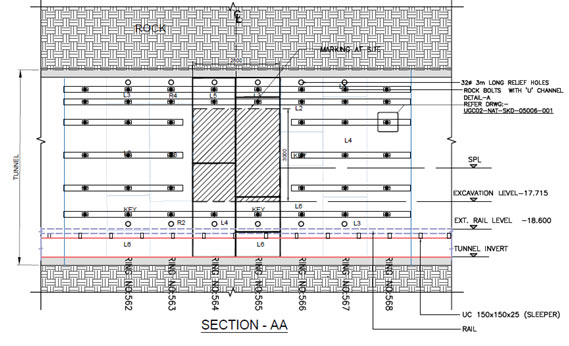
Within the 5.8m i.d. downline running tunnel, segments are marked for breakout of the three proposed concourse connection adits. Holes are drilled into the breakout segments to release any build-up of water pressure behind the lining. Temporary u-channels and rockbolts support the lining before removal of the breakout segments and against the anticipated increased stresses of adit excavation (Fig 2). The segments to be removed will be cut out with circular core drills around the perimeter.
A small 2.8m x 3m transition zone breakout from the running tunnel will give way to the larger 6.7m x 7.5m adit excavation an subsequent breakout and enlargement of the station platform cavern with the adit excavated to platform level (Fig 3).
The next phase in the sequence, to excavate the station platform tunnel and removal of the TBM lining segments to platform level, is the most challenging task: ensuring stability of the rock in crown and around the TBM tunnel as gradual enlargement progresses, excavating in the longitudinal direction (perpendicular to the existing TBM tunnel) and installing the primary support of rockbolts and shotcrete according to the rock class (Fig 4).
Excavation then progresses longitudinally to excavate the crown and platform tunnel and remove the TBM segmental lining to platform level and above a temporary invert backfill. The process in completed with drill+blast excavation and primary support of the bench and removal of the temporary backfill and invert segments of the segmental lining along the full 211.45m length of the station platform tunnel (Fig 5).
After excavation and installation of primary support for both platform tunnels, excavation of the central concourse cavern will begin, following a top-heading and bench sequence (Fig 6). Longitudinal excavation of the platform tunnels and the central concourse will progress from both TBM tunnels via Adit 2 and from the cut-and-cover access shafts at both ends towards midpoint junctions.
Following excavation and primary support, station structures will be finished with a waterproofing membrane and a final in-situ concrete permanent lining to 9.5m wide x 8m high i.d. for the platform tunnels, to 6m wide x 6.5m high i.d. for the adits and to 9.5m wide x 7.6m high for the central concourse cavern. The two-access cut-and-cover shafts at either end of the station will become the ingress and egress structures, fitted with stairs, lifts and elevators, from the surface ticket hall and on into the underground platforms. They will also provide space for electrical, mechanical and ventilation systems.
By end of February 2020, work on site was just beginning. The TBMs passed through the station zone in early and mid 2019 respectively. After completion of the first tunnel all the TBM support equipment will be removed from the running tunnels before excavation of the station can begin. Secant piling of the two access shaft boxes began at the end of 2019.
References
- Delhi Metro emerging – TunnelTalk, March 2002
- Closing in on breakthrough in San Francisco – TunnelTalk, April 2014
|
|
|
|
|
Add your comment
- Thank you for taking the time to share your thoughts and comments. You share in the wider tunnelling community, so please keep your comments smart and civil. Don't attack other readers personally, and keep your language professional.


