
- Current
-
- Stay Connected
- Marketplace
- Home Office
- TunnelTalk Account

Hydro diversion tunnel failure review 08 Oct 2020
Collapse of the diversion tunnel system around the construction of the dam and underground powerhouse for the Ituango hydroelectric power project in Colombia has caused an insurance claim that has the potential to amount to the largest insurance loss in international civil infrastructure construction history. Dean Brox, an independent consultant in Canada with a particular interest in the development of hydropower projects internationally, has reviewed the two root cause reports into the disaster, one for the project owner and one for the re-insurer, as well as additional available information, to understand the details of the disaster and know how the loss could amount to US$4 billion, equal to the budgeted cost of the project at start of construction in 2010.

Ituango dam with water being released via its spillway
The Ituango hydroelectric project in Colombia is located on the Cauca River and comprises a 235m high earth core rockfill dam and a 2,480MW underground generating station sited in the right abutment of the dam. The underground generating station comprises a large cavern with eight short headrace tunnels, eight 495m deep shafts and four nearly 1km tailrace tunnels (Fig 1). Construction of the project started in 2010 with excavation of two original 1km long x 190m2 diversion tunnels, with a cast concrete invert in each. The diversion tunnels were completed in 2013 and diversion through them commenced in early 2014. The original two diversion tunnels included the industry standard design of control gates to cease diversion of the river after completion of the dam and allow for impounding the reservoir.
After the first two years of construction, the project was running 20 months behind schedule due mainly to delays in securing access and permits. An acceleration plan was adopted to not install the control gates in the two original diversion tunnels, in order to allow an earlier start of the construction of the dam, and to instead build a third diversion tunnel, referred to as the auxiliary diversion tunnel for the entire duration of dam construction. Its excavation started in mid-2015 and was completed in late 2017. This decision was a major design change during the early stages of the project and was proposed by the project designer based, as they claim, on previous examples where high flow velocities were accepted and successful.
The project is being developed by the Public Company of Medellin under a build-operate-own-maintain and transfer approach whereby the project design was prepared by a consultant for the project client, construction is by an engaged contractor, and with progress audited during construction by a separate supervision consultant.

Fig 1. Schematic of the project and its underground works
The auxiliary diversion tunnel (ADT) was designed as a single, horseshoe-shaped excavation of similar size of each of the original twin diversion tunnels at 14m high x 14m wide (about 190m2) and about 2.3km. It was excavated by drill+blast with an 8m top heading and a 6m bench. The hydraulic criteria adopted for design of the the original twin diversion tunnels was based on the diversion of an average river flow of 700m3/sec and peak flows of 1,000m3/sec, which for each of the original diversion tunnels equates to flow velocities of 1.8m/sec and 2.6m/sec respectively, which is an accepted practice for tunnels without a full concrete lining.
It is, however, questionable that a single diversion tunnel of similar size was accepted to replace the original twin diversion tunnels. The decision implied that the ADT was expected to operate on its own, with a 50% hydraulic capacity of the original diversion tunnels, for the remaining duration of the diversion period. This continuing diversion duration was for a further one year and including two intense periods of rainfall, and based on an average design flow velocity of 5.1m/sec. This is more than typically acceptable by industry standards but was considered to be acceptable by the project designers. The designers also dismissed the need for a concrete lining or a concrete invert, based on precedent cases and the assumed geotechnical conditions.
The ADT comprised an initial 35m long straight section followed by a 33m long curved section and a straight alignment to the downstream exit portals (Fig 1). The inlet portal for the ADT was located about 125m upstream from the portals of the original twin diversion tunnels and adjacent to a topographic depression in the valley slope of the right bank. This is unlike the downstream area of sub-vertical cliffs of shallow bedrock. The slope rises gently from the inlet portal of the ADT to provide a cover of about 100m after the curved section.

Upstream intake portal of the ADT
The project is located within a geo-compressional district of northwestern Colombia associated with numerous north-south oriented major geological faults as well as east-west minor faults resulting in an area of stress relief with highly disturbed fractured rock conditions. The site includes a total of seven fracture sets and the geology has an overall high permeability.
The rock conditions encountered along the ADT comprised moderately to highly fractured gneissic and muscovite schist bedrock containing continuous sub-horizontal foliation and frequent parallel shear zones. Rock quality was described as varying generally from fair to good. Excavation support was based on the application of the NGI Q-System with Classes 1 to 3 of support varying from requirements for spot bolting and shotcrete to patterns of 6m long resin end-anchored rockbolts, on varying spacings, in conjunction with a 10cm thickness of shotcrete. Class 4 comprised HEB 160 steel ribs with 10cm of shotcrete. Unlike the original twin diversion tunnels, no concrete invert was required or placed in the ADT.
Excavation of the ADT was carried out with variable blast rounds from 4m-6m and rock support comprised mainly Class 3, with some Class 2. Spiling was added to the ground support design in attempts to control the tunnel profile. Significant overbreak was increasing the overall profile with overbreak reaching estimates of more than 7m, and in some locations not measurable. The amount of overbreak could have been predicted for the prevailing highly fractured geotechnical conditions and with the full 8m high top heading being excavated to provide adequate space to install the required 6m long rockbolts. To limit the amount of overbreak, it would have been necessary to limit the size of the excavation stages and use, for example, lateral drifts, which would have had a significant impact on progress.
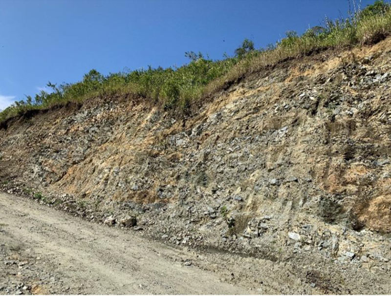
Exposed disturbed and highly fractured conditions of gneissic/schist rock
Geotechnical mapping was carried out by both the contractor and the designer and was in general agreement with installation of a conservative tunnel support. The selected tunnel support was to be agreed by both the contractor and the designer. It does not appear that a Geotechnical Baseline Report (GBR) was prepared as part of the contract as per good industry practice and as recommended by ITIG, the International Tunnel Insurance Group, to assist the bidding procedures and serve as a dispute resolution function.
Tunnel support Class 3 was installed in the area before, within, and after the collapse that included a pattern of eight, 6m long rockbolts on 1.5m spacings with two 5cm thick layers of mesh reinforced shotcrete. The findings of the two root-cause reports find that the tunnel support design was less than recommendations in the industry with only 75% of the rockbolts installed and also that the mesh layer was not installed. In addition, the installation of the rockbolts was based on the use of cement grout that required a longer time to be effective, versus the use of resin, allowing relaxation of the host rock and reducing its stability. The reports also note the lack of a concrete invert.
The two original diversion tunnels operated successfully for nearly three years after which they were plugged. The ADT operated successfully for about nine months from August 2017 until late April 2018 when it collapsed. At that time, April 2018, the project was 87% complete and eight months from start of power generation. It is the collapse that caused landslides and resulted in major damage to the underground works.
Collapse of the ADT
Flows in the Cauca River from late 2017 to early 2018 was normal. Heavy rainfall during April 2018 caused the reservoir level behind the partially completed dam to increase steadily and submerge the ADT intake portal causing pressure flow and high velocity conditions in the ADT. Actual flows during April 2018 varied from 1,400m3/sec and increased to a maximum of 2,800m3/sec. A second peak of up to 2,400m3/sec for multiple days resulted in flow velocities in the ADT of from 7m/sec to almost 15m/sec during a 15-day period.
Irregular profile and large overbreak along a section of the ADT
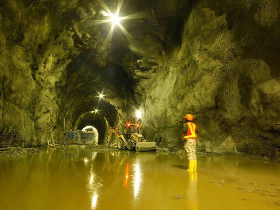
In late April 2018 the flow through the ADT suddenly decreased. This was followed by the formation of a large circular crater shaped sinkhole along the slope immediately above the ADT intake portal. With the one diversion tunnel blocked and the water level continuing to rise, the decision was made to open four of the power intake tunnels to bypass the flood flows through the nearly completed powerhouse and prevent overtopping of the nearly completed dam. This resulted in significant erosion along the floor of the unprotected power intake tunnel inverts, as well as significant damage to the electro-mechanical equipment.
With an estimated location of about 150m from the intake, the estimated volume of the crater shaped hole was 120,000m3 extending over a lateral distance of about 100m at the surface. With overbreak of about 7m in the ADT, the minimum cover of rock over the ADT after the curve is about less than 70m. The crater shaped hole revealed highly altered and discoloured poor quality rock of soil-like conditions extending to great depth of possibly 50m.
The crater shape of the collapse is consistent to the failure of crown pillars in underground mines that are associated with failures through a highly fractured rock mass, and not associated with discrete geological faults or shear zones. The large height of the collapse is similar also to other collapse examples, including that of the 16km headrace at the Kemano hydroelectric station in Canada in the late 1950s where the collapse was 55m deep.
Summary findings of root cause analyses reports
Two separate reports were commissioned by the project client and for the insurers as part of the investigations of the collapse. Referred to as root cause analyses, both reports have been made public.(1,2) Both of the root cause reports appear to have focussed on identified technical factors contributing to, or responsible for the tunnel collapse, rather than highlighting the fundamental reasons for the collapse, which are deemed to have been:
- the high flood flows that occurred during the diversion period,
- the inadequate hydraulic capacity design of the ADT, and
- the absence of a hydraulic concrete lining.

The collapse created a 100m diameter crater and sinkhole above the failed ADT
In fact, many of the technical factors listed in the reports as reasons for the collapse, are not of primary importance, as the ADT would not have functioned acceptably if these factors were adequately addressed in the design. It is noted that the identification of these technical factors was based on indirect evaluations since no inspection of the ADT has been possible to date. Valid information has been considered and these data have included review of the drill+blast overbreak, rock quality records, installed support, and hydraulic conditions.
The main conclusion of both reports is that the root cause of the collapse of the ADT was due to erosion of a discrete shear/weakness zone. This is considered to be entirely speculative, with reference in the client’s report to a single example from Norway, and for the following reasons:
- There does not appear to be any direct and convincing evidence of a discrete shear zone, presented in the reports, at or near the location of the collapse;
- There does not appear to be any direct and convincing evidence of a discrete shear zone presented in the victims’ report;(3) The resulting floods in the river also took the lives of 12 or more citizens in the villages and towns along the river.
- During excavation the Independent Advisory Panel also noted the absence of any weak ground conditions in the ADT at the collapse location;
- There is no direct evidence at the site of erosion in the ADT since there is no access;
- The possibility of erosion is inconsistent with the findings of two internationally recognized methods of empirical erosion analyses;
- Extremely large overbreak occurred along the crown area of the ADT across a 6m section from 0+542 to 0+548 and across an 8m section from 0+584 to 0+592;
- The collapse location is positioned in between the two locations of very large overbreak which represent weak areas for high pressure flow and high velocity conditions to concentrate and destabilize the rock, and manifest upwards to form a chimney to surface (Fig 3);
- A similar collapse of 60,000m3 occurred within the intake shafts without erosion as a result of overpressure of the highly permeable rock surrounding the unlined shafts;
- The circular crater shape of the collapse is consistent with a failure of a highly fractured rock mass from experience in the mining industry rather than due to a discrete shear zone, and;
- After completion of the root cause reports, observations in the intake power tunnels and the discharge tunnels, where emergency flows were diverted, clearly indicate that erosion was limited to along the invert of the tunnels without any collapses.
The root cause report compiled for the insurers infers that erosion of a shear zone at 0+540 was responsible for the collapse, whereas the root cause report compiled for the project client infers that is was a shear zone at 0+525.

Fig 2. Chimney collapse to the surface between section of large overbreak
The root cause report compiled for the insurers appears to include a key contradiction, whereby it first concludes that the design was in accordance with industry standards, and then states that the tunnel was not constructed to the design, in terms of the support requirements and the absence of a concrete invert, thus implying, indirectly, that the contractor was at fault for the works. This report also implies that the contractor was responsible for the large overbreak due to excessive blasting. However, it is fundamental industry practice that it is the project designer and construction supervisor responsible for enforcing the technical specifications regarding the procedures of excavation, the installation and confirmation of all support, to document all non-compliances and confirm the correction of all defective workmanship.
Of particular interest is that both reports do not present the original geotechnical mapping record of the collapse location near 0+525 and 0+540, but rather the record from 0+600 to 0+700, an area beyond the collapse. As there is no explanation for this, it is considered strange and not typical for such important investigative reports. It is the collapse location that is the relevant location, along with an evaluation of the as-built geotechnical conditions, and the installed support at the collapse location. It is possible that the exact record was not made available or it was not permitted to be presented, which would imply an omission of critical information for the investigative review.
Overall, both reports do not categorically state that the collapse was the responsibility of any particular party involved. However, based on standard engineering and construction practices, it is quite obvious that there were multiple and serious shortcomings with regards to the engineering design of the ADT. Also, the technical expert board that was involved during the construction of the project recommended to the project client not to build the ADT.
Alternative root cause and associated technical reasons of the collapse
As noted, the high floods of up to 1,900m3/sec during April 2018, appear to be common for the Cauca River based on a review of annual hydrology data. However, the single alternative diversion tunnel was not designed with sufficient diversion capacity for the design flows or with adequate rock support or an impermeable smooth hydraulic lining to prevent the transfer of the internal pressures into the surrounding rock mass or accommodate the high velocity flows. Given the acceptance of the single diversion capacity of the ADT by the project team, it was therefore necessary to design the tunnel with a concrete lining for the hydraulic operating conditions of high velocity and pressures flow conditions. The prevailing highly fractured and highly permeable geotechnical conditions along the ADT are recognised in the industry to be not acceptable for a shotcrete lined tunnel operating under high velocity and high pressure flow conditions. In addition, the installation of the correct amount of rock bolts (+25%) and application of tunnel support Class 4, comprising HEB 160 steel arch ribs at 1m spacings with 10cm of shotcrete, insufficient to completely encase the HEB ribs, and a concrete invert slab, would not have been effective to prevent the collapse. Spiling as pre-support is not an effective method to limit overbreak or control stability of such large tunnels in the prevailing highly fractured geotechnical conditions, when such large excavation faces were allowed by the design.

Significant erosion along invert of power intake tunnels without collapse
The ADT operated successfully during non-flood flow periods and under only limited durations of pressure flow conditions. The actual design of the ADT with traditional rock support and a shotcrete lining with an irregular profile and large overbreak, would have resulted in highly turbulent flow conditions and the development or build-up of overpressures within the surrounding rock to as high as 35m above the level of the top of the ADT for a period of three weeks and occurring under relatively low cover near the portal. This caused saturation of the rock, lubrication, and loss of integrity along weak fractures with an imbalance between the hydraulic and geotechnical conditions leading to instability and formation of a chimney extending upwards for more than 100m to surface.
After review of the available root cause reports, together with additional information and reports discovered online, the following alternative and additional factors are considered to be the primary and important reasons for the collapse of the ADT:
- Unacceptable portal location with the initial tunnel section under low cover of fractured rock;
- Single, under sized tunnel for hydraulic operations of high flood flows (only 50% of necessary design capacity);
- Unacceptable tunnel profile with large overbreak for hydraulic operations, and;
- Deficient final tunnel lining for hydraulic operations of high pressures and velocities.
All of the above listed reasons are related to the design of the ADT. None of them are the responsibility of the contractor as the applicable geotechnical and hydraulic conditions were previously known by the project designer and unprecedented critical design decisions were made by the project designer. The actual high flood flows that occurred should have been correctly mitigated through ongoing risk management practices for the project. In response to recent criticisms by the Colombian national press, the project designer has stated that the project design was in accordance with the art of engineering.
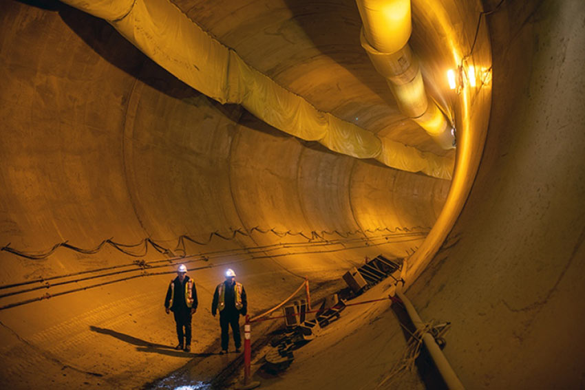
As a comparison, the 900 MW Site C hydropower project in western Canada includes two 11m diameter diversion tunnels with a reinforced concrete lining
Collapse of the ADT set back completion of the project to 70%. In late 2018 the dam spillway was completed to allow flows to pass over the dam safely and for safe inspection of the damage caused to the intake tunnels and underground powerhouse. In 2019 there were multiple studies and investigations carried out including the attempt to blast out the plugged original twin diversion tunnels, and the installation of bulkheads in the ADT to allow for repairs. Recovery and damage identification and stabilization of the underground works continues along with the planned plugging of the ADT that includes support from international consultants and contractors in various roles. The start of energy generation is currently planned for late 2021.
To date, Mapfre insurers have provided payments of USD$250 million in covered claims. The insurable limit for damages is $2.56 billion along with $628 million for loss of generation. There are indications that the ADT was not included in the environmental impact assessment (EIA) and that the environmental requirements for the project were violated. With insurance valid for all components in the EIA, legal challenges on insurance may occur in the future. The project client, with support of the Mayor of the City of Medellin, has declared its intention to commence litigation against the project designers, construction supervisors and contractors. The national media has expressed opinions that the project client is also responsible for accepting the practices and decisions made during construction that led to the collapse and the disastrous associated consequences.
Preliminary lessons learned
The collapse of the Ituango project diversion tunnel can be regarded as an error of grand proportion. The geotechnical conditions of the ADT exposed during excavation should have been immediately recognised by the designers to require a new design solution for enhanced support and lining for the anticipated hydraulic conditions of high flow velocities and high pressures. The occurrence of the collapse of the ADT is a very unfortunate situation and highlights the importance of risk management throughout the life of a project.
A preliminary key lesson learned is that the design of diversion tunnels as a critical component of major hydropower projects, must be compatible with, and respect, the anticipated hydraulic conditions including annual intense precipitation, to function safely during the entire diversion period. If adverse geotechnical conditions are realized then it is necessary to include special procedures for excavation and methods to achieve acceptable stability for the installation of the final lining. The typical industry practice comprises the design of fully concrete lined tunnels with control gates.
Author’s References
- Study of the Root Physical Cause and Complementary Report, February 2019. Ituango Hydroelectric Project. Skava Consulting (In Spanish).
- Adjusters Root Cause Analysis Report for Re-Insurers, Collapse of the Auxiliary Diversion Tunnel, August 2019, Ituango Hydroelectric Project, Authors Snee, C., Guilherme de Mello, L., Murphy, B., and Prieto, R.
- Fierro Morales, J., Aponte Rojas, D., and Quintero Chavarría, E. 2019. Analysis of geological, geomorphological, hydrogeological, and geotechnical information related to the rock mass and stability of the Ituango Hydroelectric Project, Technical Advice to the Victims, Ituango Hydroelectric Project (In Spanish)
- Independent Advisory Panel Report to International Development Bank Invest, Report No. 1, September 2018.
- Brox, D. 2019, Hydropower Tunnel Failures – Risks and Causes, International Tunneling Association World Tunnel Congress, Naples, Italy.
References
- Hydropower watercourse failures - risks and causes – TunnelTalk, March 2020
- Repairing damaged hydropower pressure tunnels – TunnelTalk, March 2014
|
|
|
|
|
Add your comment
- Thank you for taking the time to share your thoughts and comments. You share in the wider tunnelling community, so please keep your comments smart and civil. Don't attack other readers personally, and keep your language professional.