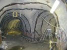
Shani Wallis, TunnelTalk
-
Beams of subatomic particles have once again started travelling at light speed around the 27km long accelerator ring of the CERN laboratory's LHC machine in search of even smaller particles of matter. Restart of the machine this week (21 November 2009), ends 14 months of work to repair electrical faults in the circuitry of the electromagnets that accelerate the beam of particles around the tunnel, which caused the shut down following its inauguration in September 2008. As the scientists hail restart of the particle smasher as a barrier breakthrough in the field of nuclear physics, this is an opportunity as well to look back and celebrate the significant civil engineering achievements that are the underground structures that house the components of the new LHC machine. TunnelTalk made a visit to the project in August 2001 to report on the challenges presented to the civil engineers and how these were addressed and accommodated.
- Underground caverns of spectacular dimension are under construction at CERN. These new underground facilities at the nuclear physics laboratory near Geneva in Switzerland will house a new high-powered detectors and the sophisticated computer equipment needed by physicists to delve deeper into particle physics and advance their quest to fathom the origins of our existence.
-
CERN, the European Organisation for Nuclear Research, is a non-profit, non-commercial enterprise established in 1953 by a group of member nations to advance the science of nuclear particle research. Today the member nations number 20 and Organisation is managed by a Council representing all member nations.
Geneva became the location of the Organisation in the early 1950s mainly because the Swiss government donated the land for the facilities and because the nature of the Organisation during its formative years favoured being, headquartered in a politically neutral country. Today, Geneva with its international airport close by is central in Europe and under the current political climate the CERN facilities are available at no charge to universities, government departments, and science laboratories from around the world to run different nuclear physics experiments. These 'customers' include institutions from non-member as well as member nations and the Russian Federation and the United States of America, as non-members, are among the largest users of the facility. Nearly 600 physicists from each nation work at CERN at various times. CERN itself employs a staff of some 2700 comprising scientists, technicians, computer operators, engineers and administrators. The annual operating budget for CERN is agreed each year by the national governments of the member nations. This is then divided into contributions from each government based on the percentage of each country's gross domestic product. CERN's annual budget at present is SFr 1 billion or about US$550 million and despite the proportional system of funding, each member state has an equal voice on the decision-making council.
Of the approved SFr3 billion ($US1.68 billion) LHC project investment, the civil engineering excavation and construction works amount to about SFr350 million (US$195 million) or about 10-12% of the cost. The largest proportion of the cost is required by the construction and installation of the highly sophisticated electronic components of the machines and the high-powered computer equipment.
The 20 member nations of CERN and the date they joined
Yugoslavia joined in 1953 and withdrew in 1961.Switzerland 1953 France 1953 Germany 1953 United Kingdom 1953 Italy 1953 Belgium 1953 Greece 1953 Sweden 1953 Denmark 1953 The Netherlands 1953 Norway 1953 Austria 1959 Spain 1961 Portugal 1986 Finland 1991 Poland 1991 Hungary 1992 The Czech Republic 1993 The Republic of Slovakia 1993 Bulgaria 1999 Facilities at CERN currently comprise a network of surface and underground structures, the largest which are two circular accelerators - the 9km tunnel ring of the SPS (Super Proton Synchrotron) pre-accelerator and the 27km ring of 4m-diameter concrete lined tunnel built in the 1980s to house the LEP (Large Electron Positron) collider. Over recent years the LEP machine has reached the end of its usefulness in terms of developing new experiments and in 1994 the decision was taken to decommission that strip out the now obsolete LEP and replace it with a more powerful LHC - Large Hadron Collider. For a total investment of SFr3 billion (US$1.68 billion), the programme was to have the LEP machine decommissioned by the end of 2000 and have the new LHC machine in operation by early 2006.
Current underground facilities at CERN lie about 100m below ground surface. In addition to protecting the environment from the radiation generated by the nuclear physics experiments, the underground dimension provides the necessary space in which to build the expansive facilities. Once made available, the superconducting particle accelerator magnets of the new LHC can be installed in the existing 27km LEP accelerator tunnel ring, with relatively few, but nonetheless significant, modifications. The massive machines of the two new LHC detectors and their associated computer control installations, on the other hand, require excavation of two new underground facilities at two additional points on the existing LEP ring. These facilities, known as the Atlas and CMS (Compact Muon Solenoid) installations, require the excavation of huge caverns up to 35m wide, 42m high and 82m long. These caverns are of up to twice the size of any existing underground structures at CERN and have required state-of-the-art approaches in both design and construction.
-
Nothing is Impossible
"The geology at CERN is far from ideal for large cavern excavations," explained Timothy Watson, Deputy Group Leader of CERN's Civil Engineering Group. "The material comprises mainly the medium strength sedimentary sandstone and marl deposits of the Tertiary Molasse over which is the water-bearing deposits of the Quaternary Glacial Moraine. The first sharp intake of breath therefore came when the physicists described the size and shape of the caverns to be hosted in these conditions. They then described that, in addition to being incorporated into the existing LEP ring, these large caverns with their several access shafts, had to be excavated as close together as possible to limit the cable connections between the detectors and the data collecting computers. The physicists would also have preferred the CMS installation at Point 1 and Atlas at Point 5. We convinced them however that it would be better to place the larger caverns of Atlas at Point 1 in the more competent of the two locations geologically."
- A second concession prised by the civil engineers from the physicists was to increase the intervening pillar between the large caverns at Point 5 from the requested smaller dimension to a minimum 7m. At Point 1 the overlaying water-bearing glacial moraine at the surface above the large span caverns of the Atlas installation is about 5-10m deep. At Point 5 the glacial moraine extends from some 55m before interfacing with the more competent practically impermeable Molasse.
- After fixing the scope and parameters of the project, the design and construction of the new facilities was divided into three construction packages - the Atlas installation in Package 1, the CMS installation in Package 2, and the necessary structural modifications of the existing LEP ring in Package 3. Invitations to bid for the design and construction contracts where issued, according to CERN policy, to consulting engineers and contractors within the organisation's 20 member nations. Designers for each package were appointed in April 1996 and contract documents were released in march 1997. These attracted bids for one or for all three construction Packages from 13 international joint venture groups and the contracts were awarded by early 1998 (Table 1). Within the bidding process for the construction contracts, package 3 was divided into two sections with Package 3B for the T18 tunnel link between the smaller and the larger accelerator rings near point 1 being advertised only in Switzerland and awarded to a Swiss only construction team.
- Table 1. Design and construction groups engaged on the LHC civil works
| Construction Package | Design Enginners | Civil Contractor | Contract Values |
| Package 1 Point 1 - Atlas Machine installation caverns and access shafts. |
A joint venture of EDF - Electricité de France (France) and Knight Piésold (UK) |
A joint venture of Zschokke Locher (Switzerland) C Baresel (Germany) and Porr-Asdag Tunnelbau (Austria) |
Sfr 80 million (US$45.7 million) |
| Package 2 Point 5 - CMS Machine installation caverns and access shafts. |
A joint venture of Gibb (UK) Geoconsult (Austria) SGI (Switzerland) |
A joint venture of Dragados (Spain) Seli (Italy) |
Sfr 113 million (US$64.5 million) |
| Package 3 Associated Structures in Package 3A and the T18 connections tunnel of Package 3B |
A joint venture of Brown & Root (UK) Intecsa (Spain) Hydrotechnica Protuguesa (Portugal) |
Contract 3A - a joint venture of Taylor-Woodrow (UK) AMEC (UK) Spie-Batignolles (France) Contract 3B - a Swiss joint venture of Scrasa/Prader/Losinger |
Sfr 100 million (US$57 million) Sfr 23 million (US$13 million) |
- During a visit by TunnelTalk to the project, each of the construction Packages was toured. At the time, construction of the underground facilities was about 50% complete. In the sedimentary sandstone and marl, excavation was
-

Fig 2. Design of the largest Atlas cavern complex
- principally by roadheader with hydraulic breakers used for harder rock intrusions. Steel-fibre reinforced wet-mix shotcrete and systematic bolting using Swellex dowels and encapsulated rebar bolts comprise the main elements of primary support.
- All underground facilities are finished with an in-situ concrete lining and have a geotextile waterproofing membrane behind. The highly sensitive computers and machines, as well as the scientists, will tolerate no dampness or water seepage at all from the underground environment. On Contract 3B, the Swiss joint venture used furbished Robbins TBM to excavate its T18 tunnel between the two accelerator rings.
- Atlas Package 1
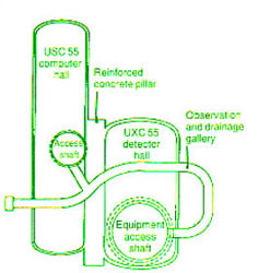
The two caverns for Atlas at Point 1 are enormous and complex in scope. The computer hall is 23m wide, 65m long and 18m high for an excavated profile of 338m2 while the adjoining detector hall is a massive 35m wide x 56m long x 42m high and 1,380m2 in section. The Molasse at Point 1 is relatively competent but it is highly variable ranging in unconfined compressive strengths from 3 to 50 MPa. As such, ground movement and displacement in the rock mass as excavation progressed would be a principal concern. -

35m span ATLAS cavern
- In addition, rather than excavating both caverns together and allowing the stresses to be redistributed as a single process, CERN requested that the smaller computer hall cavern be excavated and handed over some 18 months earlier than the other facilities in order to start installing the computer equipment as early as possible. This magnified the ground movement and displacement concerns. 2D and 3D computer models illustrated graphically both the movement of the surrounding rock towards the open space as subsequent excavation of the detector hall advanced, as well as the stresses induced in linings of the completed computer hall. Controlling these predicted movements and stresses influenced significantly the method and the excavation sequence of these two large, adjacent and interconnected caverns.
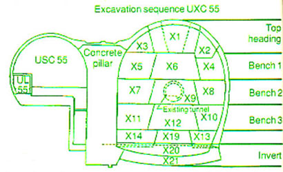
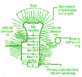
- After excavating and lining the access shafts, the 338m2 computer cavern profile was excavated first. The 104m2 vault section was excavated in a sequence of top heading drifts and the cavern taken to full depth by a series of benches. During excavation all exposed surfaces were sealed with shotcrete within 12 hours to avoid any deterioration of weathering of the marl and sandstone deposits.
-

Junction of two large shafts into the Atlas detector hall
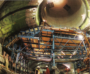
- Once the concrete of the permanent invert was cast, the concrete lining of the vault with its waterproofing membrane behind was cast using a purpose-designed formwork supplied by Bernold. To accommodate with predicted stresses as bench excavation of the adjoining detector hall cavern progresses to and beyond its elevation, the lining of the computer hall is specific in two ways. "The pre-excavated and concrete lined shafts, tied into to the concrete lining of the cavern vaults, act as huge support dowels through the rock mass," said Steven Heard, Deputy Project Manager for the Package 1 design and site supervision team, "and the concrete lining of the completed cavern itself will help reduce ground. Nevertheless, to help resist the tremendous load that will be attracted by the rigid structure once excavation of the adjacent detector hall progresses to and beyond the elevation of the completed computer hall, the 600mm thick lining is heavily reinforced, as is the end wall shared by both caverns. Half of this 2m thick adjoining end wall is cast with each of the respective cavern excavation sequences."
- Secondly, and along with the waterproofing membrane, there is a compressible layer of material installed between some areas of the computer hall's concrete lining and its primary support. This compressible layer comprises 100mm thick sheets of particular quality polystyrene that will allow for stress redistribution movement in the surrounding rock during subsequent excavation of the detector hall without placing extra load on the lining. The special waterproofing membrane for Package 1 was supplied by Guniperm and installed by Bauveg.
- During the TunnelTalk's visit, concrete lining in the vault of the computer hall was near complete. The last panel of the vault was cast in early July and that the cavern was completed and taken over by CERN by the end of July. This made the computer control cavern at Atlas the first cavern completed for the new LHC project.
-

Computer hall at the ATLAS facility
- Detector hall
Meanwhile, excavation of the enormous detector hall is underway according to its own set of extraordinary design requirements. After renovating an existing shaft to permanent standard and completing two new 14.5m and 20m diameter access shafts with their slipformed concrete lining, excavation of the huge 1380m2 detector hall cavern started with a 375m2 vault section. A sequence of top heading drifts and benches took the vault of the 42m high x 56m long cavern down to the gantry crane corbel level. - During the TunnelTalk's visit, the reinforced concrete corbels along each side of the cavern were in place and onto this the lining of the cavern's vault was being cast.
- Suspended roof
One of the most innovative designs applications on the project is a 'suspended' support for the heavily reinforced in-situ concrete lining of the cavern's 35m span vault. Computer modelling of the vault in the sandstones and marls of the Geneva Basin Molasse indicated that even with a dense pattern of rockbolts and thick layers of steel-fibre reinforced shotcrete, stability of the vault would be tested severely as the benches progresses and advance past the alignment of the excavated adjoining computer cavern to full 42m depth. To overcome these stability concerns, explained Heard, it was decided to 'hang' the vault on a system of ground anchors installed from galleries excavated laterally from the two access shafts about 15m above the cavern roof.
- From these short stub tunnels, a systematic pattern of 38 ground anchors were installed across the 56m long vault. Each of the anchors comprises a bundle of 13 steel cables pre-tensioned to a working capacity of 225t. These anchors will be tensioned from within the galleries and will act in conjunction with the lined shafts to temporarily support the vault lining. Geotechnical instrumentation including extensometers and pressure cells installed around the cavern will monitor movement and ground load increases to indicate how the anchors will need to be managed with time. Only when excavation of the cavern is complete and the heavily reinforced concrete walls are cast to the underside of the crane corbel, will the tension ties be relaxed. With time all movement will gradually cease and the stresses around the new structures will become stable and in balance once again.
- In June progress report from Switzerland, five of the seven panels for the vault's concrete lining were cast and the remaining two panels were to be cast by the end of July. Tensioning of the ties to suspend the vault was programmed for early August and excavation of the cavern with the subsequent benches was scheduled to resume at the end of August.
-

Zone of weak strata in the bottom of the Alice cavern excavation
- CMS Package 2
At point 5, excavation of the caverns and the shafts for the CMS machine is once again distinguished by the sheer size of the caverns, their very limited distance apart, and also by the generally poor ground conditions. At point 5, the 55m deep layer of upper water-bearing glacial moraine limits cover in the Molasse above the caverns to about 20m. To cope with the stresses developed during excavation under these conditions, the cavern end walls are curved rather than straight to create an inherently more stable, circular profile on all sides (Fig 3). Despite this, computer modelling confirmed that excavation of the two caverns so close together, could not be supported on such a narrow pillar of rock. "The solution, before any cavern excavation could begin, was to excavate this pillar zone and replace it with mass concrete," explained Ken Cole, the Engineer's Representative on site for the design and construction supervision team. - A tour into the underground works during the visits to CERN by TunnelTalk found this pillar excavation at its full depth, its peculiar profile outlining the eventual shape of the two caverns either side. In an approved alternative to the Engineer's method of starting at the bottom and excavating a series of individual drifts, one above the other, and back-filling these before starting the next, the contractor has excavated the full extent of the pillar before backfilling with concrete in 2m lifts.
-

Fig 3. CMS, Point 5
- The walls and crown of the 7m thick, 30m high x 50m long pillar excavation are heavily supported with 8m long fibreglass and steel dowels and layers of 30N/mm2 of wet-mix shotcrete reinforced with 40kg/m3 of steel fibre and dosed with a non-alkali liquid accelerator introduced at the nozzle. The geotextile waterproofing membrane (Stratum Q-500, 100% polypropylene and Alkorplan 35041902 PVC-P) is also being applied to selected surfaces in the pillar area before it is backfilled with concrete. Geotextile supplier was Vigano Pavitex of Italy and the installation was by EI-GCC from France. The shotcrete and the membranes is linked into the two adjacent caverns during their excavation while any rockbolts extending into the profile of the caverns are cut out during their excavation.
- Since TunnelTalk's visit, concrete backfilling of the pillar zone had progressed and on schedule to be complete in August. Meanwhile lining of the observation and drainage gallery above the cavern system was completed and the geotechnical monitoring instrumentation required was all in place. Subsequently, excavation of the large diameter access shaft was lowered to its junction with the large detector cavern and an anchored collar was being constructed in preparation for starting excavation of the cavern's top heading drifts as soon as the pillar was completed.
- Frozen shafts
One of the most significant geological impacts on planned construction of the underground facilities was encountered at Point 5 during excavation of the access shafts. The intention of design was to use ground freezing to support excavation of the shafts through the water-bearing moraine at the base of the Jura Mountains. However, unfortunately, and despite a programme of grout injection prior to installing the freeze to reduce the permeability of the Moraine, the volume of ground water was greater than anticipated. More importantly, the velocity of water flow through the highly permeable material, and particularly through the narrowing channels as the freeze began to form, was also higher than expected. - As a result, the original freezing installation had to be augmented first with extra freeze pipes and grout holes around the shaft circumference, and secondly by introducing liquid nitrogen to boost the brine freezing systems. This finally secured a ring of frozen ground for safe excavation of the shafts to the Molasse interface. The situation resulted in a claim by the contractor for extra time and cost.
-
Contractual aspects
Contracts for the new works at CERN are based on the FIDIC 4 set of terms and conditions. According to Watson, FIDIC, although Anglo Saxon in legal style, is accepted and understood by the different nations engaged on the project. In addition, CERN incorporated the following modifications to the base of contract conditions: - The authority to commit extra money to solve problems is removed from the Engineer's remit and rests solely with the CERN Engineering Group;There can be no court cases to resolve contractual disputes. Disputes can be settles only by arbitration; There can be no arbitration hearings until after the end of the contract; and, A panel of five adjudicators (no lawyers among them) nominated by CERN and accepted by the contract parties, was appointed at the start of the construction contracts to hear and recommend settlement of any interim claims. The panel is chaired by a civil engineer from Sweden and comprises rock mechanic specialists from Norway and Denmark, experienced contractors from Austria, and a contract specialist from the UK.
- The panel settled the claim with the contractor for the ground freezing extras at Point 5 and also worked on renegotiation of the Package 3A construction contract after it was awarded.
- Package 3
Package 3, and particularly the Package 3A contract, comprises the greatest degree of modification to existing structures and was influenced most significantly by the on-going operation and delayed decommissioning of the existing LEP machine. Work on site started soon after contract awards but the early phases of construction were complicated by the fact that, in order to meet the early 2006 operation date for the new LHC machine, excavation of the new facilities would have to start before the old LEP machine was decommissioned. This was exacerbated in late 2000 when the LEP was required to run for an extra month to conclude current experiments before it was finally shut down for stripping out. - As a result claims for delays and disruptions to work programmes were being added daily. As a result, in June 1999, the lump sum contract awarded in September 1998 was renegotiated as a target cost contract with the time and cost schedules recalibrated and agreed.
-
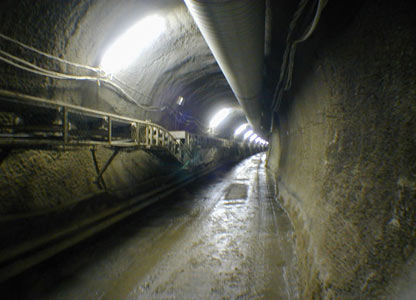
Excavation of new accelerator ring tunnel
- Since then, and particularly since decommission of the LEP machine in early 2001, work has progressed to schedule. On Contract 3A, excavation of the 2.6km long x 3.8m o.d. TI2 tunnel progressed in both directions from the intermediate oval-shaped access shaft using a Voest Alpine AM50 roadheader. By mid-April 2001, excavation was complete and installation of the in-situ concrete lining with an Ewald Dörken Delta MS drainage geotextile behind was in progress.
- On Package 3B, the Swiss construction JV had completed excavation of the 2.5km TI8 tunnel using a 3.6m diameter Robbins TBM as a contractor's alternative. Two particular geological problems were experienced during excavation of the TI2 and TI8 tunnel structures. First there were isolated rockfalls as in situ stresses in the over consolidated molasse were released with excavation. In the smaller diameter tunnels these were not serious and caused no injuries but they did slow progress. Second, there was a swelling or heaving reaction of certain clays and marls when in contact with water introduced by the excavation process. Invert heave of as much as 300mm was subsequently re-excavated and leveled prior to being lined with concrete. Rockfalls were minimized with the installation of extra rock bolts in certain areas and with a thickening of the shotcrete primary support.
-
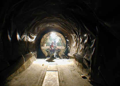
Final lining and drainage membrane
- "The TBM alternative on Contract 3B promised a shorter excavation period with progress rates of up to 17m/cay working three 8h mining shifts/day, "said Mike Lepper for the design joint venture. "Unfortunately it too suffered delays due to rock falls and took longer than anticipated to finish." The TBN was launched in August 1999 and after completing its 2,200m drive in June 2000, it was dismantled and removed through the working shaft. In-situ concrete lining of the TBM tunnel with the drainage membrane waterproofing system behind was underway when visited. Connections into the existing accelerator rings at either end of the tunnel were scheduled to start in July 2001 using roadheaders.
- According to a progress report in early June 2001, the connections of the Contract 3A TI2 tunnel into the existing accelerator rings were complete and a 300m length of lined tunnel had been isolated behind a radiation door to allow the SPS accelerator to recommence operation.
- On Contract 3B, the invert slab to the TI8 TBM-driven tunnel had been cast; the access shaft, main chamber and short section of tunnel to the SPS ring connection was complete and had been handed over to the client; and the contractor had started roadheader excavation of the closing length of tunnel into the LEP accelerator ring and on the new chambers required at Point 8. This broke through in early October.
- As the underground facilities progress into the later stages of excavation, the contractors on each Package have also worked on construction of new surface facilities. In these facilities the components of the massive detector machines and the sections of the electro-magnets to be installed in the underground tunnels and changers are being assembled and prepared for installation. By mid-June 2001, progress was more than 60% through the civil works program and the project was on track to have all excavation completed by mid-2003 and the new LHC machine in operation by the due date of early 2006.
-

Completed section of the Package 3A T12 tunnel
- Two particular geological problems were experienced during excavation of the TI2 and TI8 tunnel structures. First there were isolated rockfalls as in situ stresses in the over consolidated molasse were released with excavation. In the smaller diameter tunnels these were not serious and caused no injuries but they did slow progress. Second, there was a swelling or heaving reaction of certain clays and marls when in contact with water introduced by the excavation process. Invert heave of as much as 300mm was subsequently reexcavated and leveled prior to being lined with concrete. Rockfalls were minimized with the installation of extra rock bolts in certain areas and with a thickening of the shotcrete primary support.
- Meanwhile, in new facilities on the surface, the components of the massive detector machines and the sections of the electromagnets to be installed in the tunnels and the set of complex, massive, and extremely impressive underground chambers are being assembled and prepared for installation. The project is on track to have all excavation completed by mid-2003 and the new LHC machine in operation by the due date of early 2006.
-
Underground triumph at CERN - TunnelTalk, Sep 2008
CERN
Gallery
|
|
|
|
|
Add your comment
- Thank you for taking the time to share your thoughts and comments. You share in the wider tunnelling community, so please keep your comments smart and civil. Don't attack other readers personally, and keep your language professional.


