
- Current
-
- Stay Connected
- Marketplace
- Home Office
- TunnelTalk Account

Designing a 100km collider tunnel for CERN 10 Dec 2014
Long-term civil engineering plans don’t come much more ambitious than those of CERN, the 21-nation strong European Organization for Nuclear Research. A contract is already awarded to Arup to undertake conceptual design studies for both the tunnel engineering and geotechnical aspects necessary for completion of the 80-100km long Future Circular Collider (FCC) that may, by 2035, complement the existing 27km Large Hadron Collider (LHC). Like the particle accelerator that it will supersede, the new underground facility would be centred on Geneva in Switzerland, with overspill into neighbouring France. John Osborne, head of CERN’s future projects civil engineering team, talks to Tunneltalk News Editor Peter Kenyon about the future underground construction plans that are currently on the table.
It is sixty years since the first particle experiments began at CERN – the European Organization for Nuclear Research – and the one thing that has characterised its growth from humble beginnings to world’s leading underground particle physics facility has been a preference for making a start on the long-term planning of future developments almost as soon as the previous one has become operational.

Robbins TBM final breakthrough on the initial SPS tunnel (July 1974)

Wirth TBM breakthrough between Point 2 and 3 of the original LEP tunnel (1988)
The first such programme saw construction begin in 1972 of the first of CERN’s underground circular colliders – the 7km long Super Proton Synchotron (SPS). Excavated by a Robbins TBM at an average depth of 40m below the surface, tunnelling was completed in two years (1974), with the SPS firing up in May 1976.
Almost as soon as the SPS came online, a 20-year programme of design, construction and scientific experimentation was being devised for its successor – the 27km-long circular Large Electron-Positron (LEP) collider tunnel that would be constructed in the 1980s, coming online in 1989. This facility incorporated 32.6km of tunnels and bypass tunnels of all diameters, as well as 37 caverns and 19 access and ventilation shafts.

CMS experimental station cavern measuring 53m x 27m x 25m (2005)
This was followed by the even more ambitious Large Hadron Collider (LHC) project of the 1990s and 2000s that culminated in the underground construction of two new deep-level experimental stations (Atlas and CMS) along the original LEP tunnel alignment, in addition to more than 30 new caverns, 6.5km of new tunnels and six new shafts for installation of the next generation of particle accelerator equipment (Fig 1, below).
All of this long term planning culminated in 2013 with LHC particle collision experiments that proved the existence of the hitherto elusive Higgs boson, a particle of monumental importance to physicists attempting to undestand the origins of the universe and its subsequent expansion. Until that moment the particle had been theorised but never proven to exist.
The Future Circular Collider
In comparitive terms, if the LEP placed a proverbial magnifying glass over the mysteries of particle physics, and the LHC increased the magnification factor to zoom lens proportions, then the planned FCC aims at developing the sub-atomic window still further by applying the microscopic view necessary to take the science to yet another level.
For physicists to achieve this, however, will first necessitate construction of an 80-100km underground circular collider tunnel, plus associated shafts, experimental galleries, and large caverns that will be needed to house all the very latest hi-tech equipment.
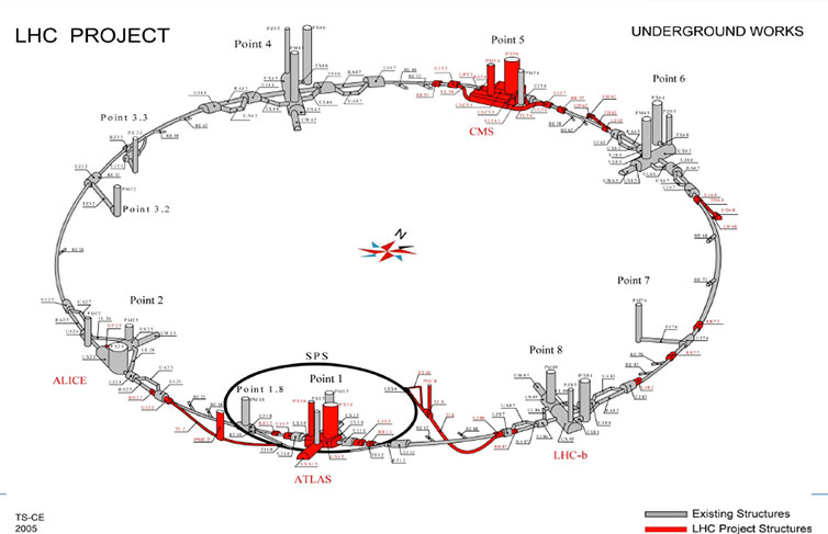
Fig 1. Underground infrastructure and alignments of the SPS, LEP and LHC collider tunnels
The brains who currently use CERN’s existing underground laboratories to conduct their experiments in sub-atomic particle-smashing at near light speeds will always want longer tunnels, more advanced accelerators, and an optimal rate of collisions (or “luminosity”, to give it its technical name). It is the job of the designers and the civil engineers, like John Osborne, to accommodate the physicists’ wishes as best they can – given the real-world contraints of technical feasibility, geological reality, risk management, not to mention cost.
To that end Arup was engaged in January (2014) to assist in conceptual design studies and to identify optimal underground alignments in time for the next major update meeting (due in 2018) of the European Strategy for Particle Physics – which in 2013 took a decision in principle, subject to technical feasibility and cost, to advance the Future Circular Collider (FCC) project. Other key partners include Amberg Engineering, and Géotechnique Appliquée Dériaz (GADZ), as part of ongoing efforts to more precisely map out the geological conditions that can be expected in undertaking such an enormous venture, exploring the technologies that are available to overcome the challenges presented, and coming up with a risk- and cost-optimised recommendation.

Fig 2. Arup’s BIM software as it relates to CERN design
Key to this process is the design and utilisation of a 3D Building Information Modelling (BIM) system that enables all the project’s partners to explore at the click of a mouse the relevant obstacles and variables associated with different alignments, geological profiles, gradients, shaft locations and depths (Fig 2). Such modelling software is increasingly being scoped to include 4D (time) and 5D (cost) elements, and enables different scenarios and preferences to be reported back quickly and efficiently.
“Arup has developed a dynamic Web-based GIS application, which integrates numerous existing geological data sources, incorporating the geological, tunnelling and particle collider system constraints in a user-friendly digital environment,” explained Arup Project Director Matt Sykes.
“Using BIM this early on in the design process is invaluable. It allows us to make critical decisions using data that can be easily visualised, enabling the team to make decisions with a clear overview of the multiple, highly complex components of this ground-breaking project,” he added.
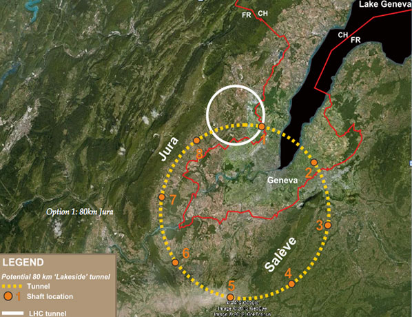
Fig 4. Lakeside alignment (90% molasse)

Fig 5. Jura Mountains alignment (90% limestone)
Overriding geological considerations present in CERN’s locality around Geneva have focused the search on what is known as the “Lakeside” ring (Fig 4). Osborne told TunnelTalk that early “pre-prefeasibility studies” had discounted the “Jura” ring (Fig 5) on account of its complex geology and the very real threat of having to excavate up to 90% of the alignment through the potentially karstic limestone of the French Jura Mountains. Another down side of the Jura ring would be the need for exceptionally deep shafts and high overburdens – up to 1,270m in some places. To put this into perspective, shaft depths along the current ring reach up to 140m, for an average of 100m. Also discounted is a shorter 47km Lakeside ring which does not match the physicists’ requirements.
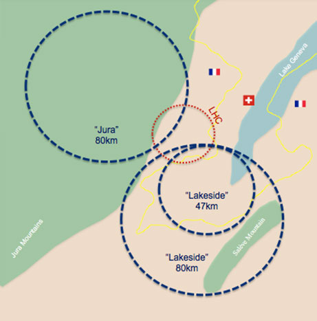
Jura and Lakeside alignments transposed
“Looking at these two broad 80km paths – one on the Jura side and one under Lake Geneva [or Lac Leman, in French] – was our starting point,” explained Osborne. “We looked at the risks of each and concluded pretty quickly that the Geneva basin was the better option.”
Given that the FCC is constrained by the likely need to connect to the existing LHC facility (which would be used to feed particles into the new construction), the search is now focused on a conceptual design ring that would connect on the south side, through a predominant geology of molasses characterised by the more TBM-friendly sandstones and marls. Only about 10% of this route would have to pass through the limestone in the Mandallaz and Jura Mountains.
The original LEP tunnel, which forms the basis of the existing LHC facility that replaced it in the 2000s, was constructed between 1985 and 1988 – largely by a mix of roadheader and 3 x 4.5m diameter Wirth TBMs, but with drill+blast excavations taking place over the short reach (Point 3 and 4) that traversed the lower Jura Mountains on the north side of the ring.

Risk assessment of the early concept alignments
Practicality and history weigh heavily against anything but minimal contact with limestone formations for the construction of the FCC, although Osborne concedes that technological capabilities for managing the challenges associated with excavation of the potentially karstic sections are better now than they were during that initial construction period some 30 years ago. “We had a bad experience with the limestone during construction of the drill+blast sections of the original LEP tunnel construction in the 1980s, and we still have problems today with water ingress between Points 3 and 4 sections of the tunnel through the Jura limestone,” said Osborne (Fig 1).
At this very early stage the conceptual design is looking nominally at 12 deep access shafts, located at significant locations intervals along the ring. This would likely mean “at least six” TBMs being required to complete individual headings of between 8-10km, depending on the size of the ring that cost and risk assessments identify as optimal. “This was based on what we thought was reasonable for safety and for access and for services to get into the tunnel, although of course it has not been defined yet,” said Osborne. “At this stage the most optimal alignment that we have identified is 93km long. This is a nice ‘fit’ [geologically and depth-wise], though uncosted.”

Proposed Japanese drill+blast profile for ILC
Cutterhead size and configuration is as yet unknown, but somewhere in the region of 5-6m appears likely. The possibility of a twin-running tunnel is also being considered, Osborne told TunnelTalk. “There could be one tunnel for the machine and one for the services, but that is still up in the air at the moment since it would obviously cost a lot of money.” Another possible option might be to divide a larger diameter single bore with a concrete radiation shield down the middle, thus effectively splitting a single bore into two separate halves.
A drill+blast version of this type of “two-half” configuration is in early design in Japan – an "special observer" partner of CERN – where a site has been identified in the north of the country for the construction of what would be a 30km-long straight line International Linear Collider (ILC) machine.
But as far as excavation methods for the FCC in Switzerland and France are concerned, the balance between TBM, roadheader and drill+blast excavation around the full circumference of the tunnel is yet to be decided. “It’s too early to say with any degree of precision what excavation methodologies will be used,” explained Osborne. “Some of the tunnels are going to be quite deep. The earliest outputs from the Arup modelling tool are showing that some of the shafts are going to be up to 300m deep, and in some areas there will be more than 500m of overburden. It would be nice to think that we can do all the excavation through the competent molasse rock with TBMs but there is a risk of squeezing that we haven’t really understood yet, although Amberg are likely to be engaged to study in more detail the tunnelling methodology.”

Site A is preferred Japanese site for the 30km ILC
“Basically the Arup tool will deliver three or four alignment options and then we are going to look at each in more detail with Amberg engaged to look at the type of machines that will be best suited to the geologies of each location.”
To make matters more complex from a visualisation and planning perspective, the curvature of the earth has to be taken into consideration in any future design path. This means that the “flattened” satellite imagery available across the diameter of any potential alignment for the FCC has to be compensated for in the virtual modelling. This curvature (3D) versus flattening (2D) effect accounts for a differential of up to 100m across the diameter of an 80-100km ring, and the alignment is further restricted by a maximum slope of 1-1.5% across the whole circumference for the complicated cryogenic and magnet installations to work effectively.
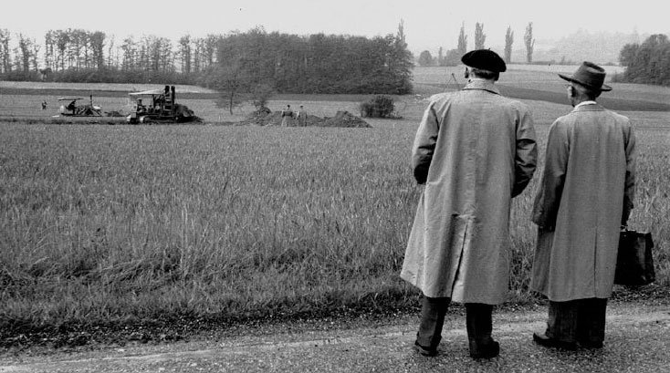
Day 1 of CERN construction (1954)
“It gets quite complicated because if we were to use sea level as our reference point this would imply horizontal. If it were the same distance above sea level around the ring then you would not be in the same plane because the machine would be following the earth’s curvature,” said Osborne. The best way to imagine it, he explained, is to think of the FCC as an enormous fixed disc that needs to be sunk in its entirety into the earth in order for it to be in the same plane.
With the effect of the earth’s curvature having considerably greater impact upon the necessary depth considerations for the larger FCC as compared to the 27km LHC, early calculations show that for an 80km ring, and to remain within slope parameters, the shafts might have to be at an average depth of 270m with a maximum overburden along the tunnels of up to 670m. This compares to an average shaft depth of 100m for the LCC, and a largest overburden of 170m.
What is more, the Lakeside route that is currently under investigation is further complicated by the likely need to cross under Lake Geneva.

Geological profiling for a circa 100km FCC alignment
“This is one of the key factors,” Osborne told Tunneltalk. “We have three possibilities; one is to be in the competent molasse rock that is quite deep, or we can come less deep into the glacial deposits that are in the moraines, which is a bit more complicated but not impossible. But there is a third idea that has come out of an open brainstorming exercise where no idea is laughed at.” This would involve construction of an immersed tube tunnel under Lake Geneva which would facilitate much shallower construction depths across the whole of the flat-lying Geneva basin.
“To be in good molasses below Lake Geneva we have to be about 170m below the water’s surface. In very broad terms, to be in the glacial moraines under the lake you can come up by a further 50m, but for the immersed tube option you can come up by a further 50m in this location,” explained Osborne.
Being able to utilise the shallower depth under the Lake Geneva basin could have a “big, big impact” upon the overall design of the FCC machine, and has the potential benefit of enabling shallower configurations at the opposite end of the ring where the alignment crosses the Mandallaz mountain range and heads towards the Alps and the famous ski slopes at Chamonix. “This could have a huge impact, and it is very interesting to look at these three options; this is part of what we will be doing over the coming years,” said Osborne.
As with all long-term infrastructure plans, all that is certain at this stage is completion of a five-year conceptual planning phase with regular updates on progress – the next one scheduled to be delivered at a high-profile conference in Washington DC in March next year (2015). Nothing in this business, however, is certain. “By the time of the Washington workshop in March we should have narrowed the study down to three or four options which we will then go away and look at in more detail, but something might come up that we didn’t anticipate and things could all change again,” said Osborne.
TunnelTalk will, of course, report on developments on this most mega of mega-projects, as they arise.
References
- The Hadron Collider – construction of great excavations – TunnelTalk, August 2001
- Iconic underground structures – TunnelTalk, September 2010
- Spectacular excavations for physics research – TunnelTalk, August 2001
- Particle experiments the goal at Hamburg – TunnelTalk, August 2012
|
|
|
|
|
Add your comment
- Thank you for taking the time to share your thoughts and comments. You share in the wider tunnelling community, so please keep your comments smart and civil. Don't attack other readers personally, and keep your language professional.