Subsea connection for desalination plant
Aug 2008
By Carla Carroll, Senior Communication Consultant for the GCD Alliance
Edited by Shani Wallis
-
Twin 2.2km long x 2.8m i.d. tunnels bored out under the sea off the coast of Queensland are the vital lifelines for the new Gold Coast Desalination plant in Australia. The principal design criteria for these saltwater conveyance tunnels and the construction and programme constraints are discussed.
- Of the options available, the GCD Alliance proposed bored tunnels under the seabed as the most acceptable and durable solution for the intake and outlet connections to the new desalination plant at Tugun.
-

Construction site
- This part of the Queensland's famous Gold Coast just south of Brisbane, is a popular tourist destination and a sensitive marine life habitat. In addition to environmental sensitivity, the nature of the sea floor, strong ocean currents and the potential for cyclone storm conditions supported the use of tunnels rather than laying pipelines.
- Of four international groups that showed initial interest in 2005, the GCD Alliance, in a short list of two, was awarded the contract to design, build and operate the facility for 10 years.
- The GCD Alliance is an un-incorporated group of companies that includes Australian contractor John Holland, water operating company Veolia Water Australia, and design engineers Halcrow for the tunnels, Sinclair Knight Merz for the plant, and Cardno for the distribution pipelines. Under the Alliance contracting model, a 'total outturn cost' is set and all parties share the pain/gain of any cost over or under runs. The agreed $Aust 1.12 billion fixed cost for project development takes the project through the siting, feasibility, design and construction phases.
-

View into lined 2.8m i.d. outlet tunnel
- The Alliance form of contract is favoured in Australia and requires that the client's team is imbedded in the contractor's team to achieve a 'best for project' outcome. After operating the plant for the first 10 years, and with an option for a further five, ownership and operation reverts to SureSmartWater, a sole shareholder company owned by the Queensland State Government.
- The GCD Alliance was commissioned in November 2005. The final contract was signed in November 2006 and construction mobilized immediately. A tight 24-month construction period is driven by a legislated delivery target date of 30th November 2008 to have the plant delivering its first fresh water. The area is suffering the worst drought in the region's recorded history and water storage levels were at record lows when work began. The plant will deliver 125 megalitres of fresh drinking water per day when it comes on line in November.
-

Plan of the two tunnel alignments
-
Tunnelling
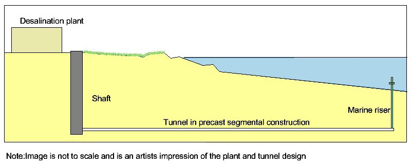
Connection to the ocean is via the two under sea tunnels, the 2.2km long intake collecting seawater and the 2km long outlet tunnel returning brine to the ocean. From two 70m deep access shafts on the six-hectare site at Tugun, the two tunnels rise on a 1:1000 incline towards risers to the ocean floor about 1.5km offshore. Maximum depth below sea level is 70m to tunnel invert with a minimum 47m and a maximum 60m cover to the seabed. - The two 10m diameter slurry diaphragm walled access shafts were completed in about three months and ready for delivery and launch of the two 3.4m diameter Herrenknecht Mixshields selected to drive the subsea tunnels. Starting in June 2007 the two 150-tonne slurry machines progressed on an uninterrupted 24 hour/day, 7 day/week production schedule to complete both tunnels by the February 2008 programme date.
-

TBM components ready to be lowered down the access shafts
- Tony Bermingham, Project Manager of the tunnelling and marine operations for the Alliance said: "We chose the slurry tunnelling method because it is the safest and most robust method for this job. Given the time constraints, we had only limited geotechnical information available to us at the feasibility stage and maximum hydrostatic pressure under the full head of water was a potential 7.5 bar."
- Bermingham comes to the project after working on a number of major tunnelling projects in his international career, including the Channel Tunnel, the Athens Metro, the slurry TBM operation for the Thames Tunnel on the Channel Tunnel Rail Link into north London in the UK, and the SMART highway and stormwater control tunnel in Kuala Lumpur, Malaysia, that employed two 13m diameter Herrenknecht slurry Mixshields. He is assisted on the desalination plant project by Tunnelling Manager, Matt Lennon and Marine Manager, John Holmes. This is only the second time slurry tunnelling has been used in Australia. The first was for the airport rail link in Sydney as a lead up to the Sydney Summer Olympic Games in 2000. Given the tight construction time frame, two machines were needed on the desalination plant to drive the relatively short 2km drives simultaneously.
-
Mixshield advance under the sea
Each 3.4m diameter cutterhead on the Aust$10 million, purpose-built Mixshields is dressed with 24 disc cutters to work through a bedrock of high quality but fractured metamorphic siltstone (argillite). With an average compressive strength of 120MPa, most of the 52,000m3 (approximately 125,000 tonne) of excavated siltstone separated at the surface bentonite treatment plant is of sufficient quality to be used as engineered fill in the neighbouring Gold Coast Airport area. - The tunnels are lined with precast concrete segments. "The segments are the primary and final lining," said Bermingham. "The tight schedule allowed no time to fabricate and install an internal secondary pipe lining. We therefore had to ensure a concrete lining durable enough to cope with the constant flow of saltwater over the specified 100-year design life."
-

Mould for production of the trapezoidal segmental lining

- To meet the criteria, the six trapezoidal segments in each 1.2m wide x 2.8m i.d. ring are steel fibre reinforced (SFR); have a compressive strength of 50MPa; a first crack flexural strength of 4.6MPa; and are quality benchmarked to Quality System AS/NZS ISO 9001:2000. To ensure durability and strength, and to minimise porosity, the concrete mix includes silica fume and fly ash as well as a high-range water reducer to provide a low 0.35 water/cement ratio; and 35kg/m3 of steel fibre for corrosion resistance, ductility and durability.
- This is the first use of trapezoidal SFRC segments in Australia. Tunnel designer Halcrow promoted the trapezoidal design to ensure structural integrity of each tunnel and allow rapid installation and negotiate tight radius vertical and horizontal curves. All longitudinal joints are offset by 10 degrees to the axis of the tunnel and the circumferential joints taper from 1193mm to 1207mm. With plastic dowels on the longitudinal joints and mild steel bolts on the radial joints, crews using the vacuum segment erectors could build a ring in about 11 minutes. All bolts on the radial joints are removed to avoid durability problems during operation of the saltwater conveyance tunnels.
- The 20,000 segments used in the tunnels were fabricated under Alliance subcontract by Precast Concrete Products in Wacol, Brisbane. Precast Concrete Products also fabricated the 48 moulds used in the casting works. Tests on mould dimensions, materials and concrete were conducted for each shift and the moulds were subjected to significant tolerance testing after every 500 casts. Segments were trucked the 100km or so from the yard to site.
-

Ring build area of the TBM

Operator's console on the TBM's backup
- The journey of each TBM followed a precise route controlled by the VMT guidance system on each TBM and co-ordinated by a GPS survey grid. From start to finish, each TBM progressed at about 75m/week working two 12h shifts/day, 7 days/week.
- During construction, TBM cutterhead interventions were carried out once every two days as a planned minimum. Compressed air conditions of up to 3.5-bar were needed to hold back ground water inflows recorded at up to 3,000 litres/min. Team members had to spend up to two hours in the hyperbaric chambers after each maximum 4hr maintenance intervention at 2.4 bar to safely decompress to normal atmospheric conditions. About 10 specialised tunnellers, including TBM operators and tunnel constructors, worked on each TBM shift. Access in the shafts was via an Alimak lift and five six-tonne Plymouth diesel locomotives transported equipment, materials and crews to and from the TBMs in each tunnel. The ventilation system on each tunnel was required to deliver a minimum 4.6m3/sec of fresh air into each dead-end heading. Approximately 100 tunnellers/day in two 12-hour shifts worked both tunnels, above and below ground.
- "The most significant concerns of the slurry excavation experience," said Bermingham, "was wear of the pipes and pumps and the need to change cutters under 3.5 bar compressed air. The salty ground water had no effect on the TBM but it did affect the bentonite, slowly destroying its properties and reducing its effectiveness. Bentonite consumption averaged 6kg/m3 of excavated rock for a total 240 tonne used for both tunnels." The most significant concern for the job was sourcing experienced labour. "There are only a limited number of TBMs being used in Australia," said Bermingham, "and 98% of our workforce had never seen a TBM. Key people were brought in to educate the locals who responded well to the challenge."
- Once the TBMs reached their dead-end destinations, about 80% of each was recovered, leaving the shield sections buried deep under the seafloor.
-

Installation of the risers some 1.5km from Tugun
-
Marine works
Offshore, a self-elevating platform barge was used to construct the 40m deep marine risers, one for each tunnel. These were installed after finish of the TBM drives and a cross-passage excavated from the completed tunnels made the final connections. These 2m diameter x 4m long cross-passages were excavated using traditional hand mining with steel sets and timber lagging support through ground pre-treated with cement grout injection. - For the risers, a 120-tonne piling-hammer on the barge drove a 3m diameter steel caisson to depth. Into this, the 1.5m-diameter fibreglass reinforced riser pipe was installed and the annulus backfilled with high strength concrete to form a reinforced concrete riser.
- During plant operation, the intake tunnel is gravity fed at approximately 0.5m/sec through a low velocity head cap. This is less than ambient sea current to minimise capture of sea organisms.
- The riser for the outlet tunnel is fitted with a high efficiency diffuser to disperse the brine in a relatively small mixing zone of about 120m x 225m. This plant is one of only two in the world to separate back wash material before returning salt water to the ocean. At the edge of the mixing zone, salinity is modelled to be almost at ambient salinity levels.
- After starting in July 2007, both tunnel drives were completed on time in February 2008 and the tunnelling and marine programme works are on track for scheduled commissioning of the plant in November. Operating at 100% capacity, approximately 334 megalitres of seawater each day will be fed into the plant to produce 125 megalitres of fresh drinking water. This is approximately 20% of South East Queensland's water needs. Initiated originally by the Gold Coast City Council, desalination was chosen by the community in 2005 as its most favoured fresh water option that did not rely on rainfall or other surface water-storage methods. The plant forms a vital part of the State Government's new Aust$ 9 billion South East Queensland Water Grid that is designed to secure water supply to the 3 million people who live in the service area, a population that is projected to rise to 5 million over the next 50 years.


