San Vicente stumped by tough conglomerate
Sep 2007
Shani Wallis, Editor
-
Progress on the San Vicente water aqueduct tunnel in Southern California has been slowed considerably by more strongly cemented conglomerate than anticipated. The circumstances and consequences of the delay were explained to TunnelTalk visited the project in September 2007.
- An exceptionally hard matrix holding the rounded cobbles and boulders of the Stadium and Friars Conglomerate has brought progress on the San Vicente water tunnel project in San Diego to a crawl. The 17.5km (11 mile) tunnel for the San Diego County Water Authority was programmed to be in operation by December 2008 but with some 80% or 14km of the 3.9m (13ft) diameter pipeline tunnel passing through the conglomerate, this could be delayed until well into 2010.
-

San Vicente Portal
- “The conglomerate was expected to exhibit loose raveling behavior when excavated,” explained Mike Jatczak, Project Manager for the Traylor-Shea JV. “This just hasn’t proven the case and our first claim for DSC [differing site conditions] has been accepted.”
- The problematic conglomerate is encountered through the longest three of six geological reaches on the 17.5km alignment. As the most multifaceted tunnel currently underway in North America, design engineers Jacobs Associates specified three different excavation methods to cope with the different geological reaches. Conventional excavation, using drill+blast or an excavator, with steel ribs and timber lagging for primary support, was mandated for the fractured and weathered water bearing granite of Reach 5, with drill+blast also needed for the hard rock intrusion of Reach 3. A hard rock TBM was needed to manage the strong igneous and metamorphic rocks of Reaches 1 and 6 at opposite ends of the alignment, and the JV selected an open digger shield method with a precast concrete segmental lining to provide safe and secure excavation of what was expected to be weak, potentially raveling conglomerate through the long drives of Reaches 2 and 4 (Fig 1).
- The 42-month contract was awarded in June 2005 to the Traylor-Shea JV for the lowest of three bids at $198.4 million. Parsons Engineering was awarded construction management.
- After establishing four working sites, tunnel excavation began toward the end of 2005 with drill+blast in both directions from Slaughterhouse Shaft through Reach 5. Where the design was for steel ribs and lagging, Traylor-Shea presented a NATM-type alternative using lattice girders, shotcrete, rockbolts, and a toolbox of other NATM support elements. This was accepted and the JV engaged BeMo, the US division of Benton-und Monierbau, to provide technical assistance and experienced supervision.
- In May 2006, a refurbished Robbins TBM was launched at the San Vicente Portal to complete the 1.2km hard granite of Reach 6 to junction eventually with the east heading of NATM from Slaughterhouse. At about the same time, the first of two new digger shields from CTS arrived on site and was launched at Central Shaft to work westward through the Stadium Conglomerate of Reach 4.
-

Fig1. Longitudinal section of the tunnel, its six geological reaches, and its access shafts
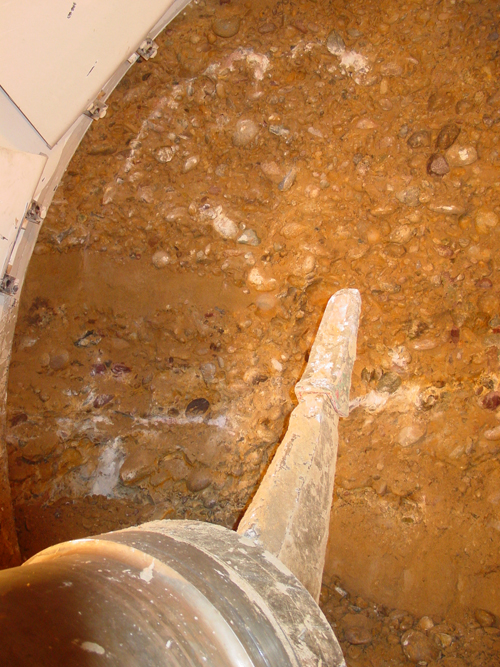
- “It was soon into this drive that the conglomerate proved much harder than anticipated,” explained Jatczak. “It is not that the rock component of the conglomerate is harder than expected. It is the surrounding matrix that is causing the troubles. The GBR notes a maximum UCS of the matrix at about 5,000psi. Most of it was to be under 150psi. When tested, though, the matrix by itself has produced many UCS results of 10,000psi and up to 16,000psi. Rather than falling out of the face or raveling when touched, the digger shield boom at times is actually breaking up the boulders and cobbles of the conglomerate as well as the hard cementing matrix. This has been heavy going and wear of excavation tools has been very high.”
-

Tunnel alignment
- The boom of the two CTS digger shields can be equipped with either a roadheader or a pick. When flipped around the boom also serves as the mucking paddle, drawing material to the central transfer conveyor and on to the main conveyor back to trains of muck skips. The excavator boom travels on runners fixed above spring line in the shield and is activated by a central 20.3cm diameter x 2.74m stroke hydraulic ram in the upper part of the shield. The operator controls the boom from his console in a forward position in the lower right hand side of the shield and to one side of the boom carriage and muck conveyor.
- The first digger shield delivered was fitted with a pick tool. The roadheader booms have not been used so far. The wear of the pick tools however is several times higher than anticipated. “We have been tearing through teeth at up to 19 per 8h shift,” said Michael Krulc, Assistant Project Engineer for the JV. “The material is so hard, sparks fly as pieces of metal break off. It is taking more than twice as long as expected to excavate a 1.2m round. On some occasions it has taken up to 5.5 hours to excavate a round.”
-

Ripper at work
- Critical path shifts As a consequence of the much slower progress through the conglomerate, the critical path on the long tunnel has changed. To begin with, the drill+blast heading west away from Slaughterhouse Shaft through Reach 5 was the critical path but subsequent events have worked to both advance and delay progress.
- First there was good news. At the end of the 1.2km drive through the fresh granite of Reach 6, the JV requested and received permission to keep the 3.5m diameter TBM going through a predicted zone of conglomerate that didn’t materialize and into the weathered granite of Reach 5. “Although we had to slow the TBM down to get through the fractured, weathered rock, it did save us three months on what it would have taken to complete that last 400m by drill+blast,” said Jatczak.
- The TBM broke-through into the dismantling chamber at the end of the east drill+blast heading in January 2007. After being backed out and overhauled, it was transported to the opposite end of the job, reassembled at the bottom of the West Shaft, and launched in April 2007 into its second 1.5km drive through the fresh granite of Reach 1.
- The second CTS digger machine was to be introduced at Slaughterhouse and walked through the drill+blast of Reach 5 west to the conglomerate of Reach 4. This however was delayed because the transition from weathered rock to conglomerate continued past the anticipated station. Drill+blast continued for an extra four weeks through a further 30m and with still no sign of the conglomerate, the JV tested the rock strength and determined that the weathered granite could be excavated using the digger shield. The CTS2 machine was eventually launched in April 2007 with muck trains traveling back through the completed drill+blast and TBM reaches to the rota-dump discharger at the San Vicente portal.
-

Spare picks on standby
- The digger shield made good progress through another 70m in which weathered granite persisted in the face in some percentage, and until it reached the strongly cemented conglomerate of the Friars Formation. Like the Stadium Conglomerate for the CTS1 machine heading west from Central, this material is also substantially tougher than predicted by the GBR. Where program advance rates of 28.3m/day were anticipated, the CTS2 machine from Slaughterhouse Shaft had recorded less than 5m/day as an average to early December.
- “With both CTS machines making seriously slow advance, the critical path is now on the longer CTS2 drive through Reach 4E to Central,” explained Jatczak. “With only limited space and restricted access, it is difficult to open an additional heading to work eastward from Central. As it stands right now, the CTS machine coming from the east has to complete the drive to Central. We are therefore concentrating on improving progress on this machine, to get excavation of San Vicente to Central section completed as quickly as possible.”
- In mid-November, the CTS2 machine was 700m into the Reach 4E drive with a further 5,900m to reach Central Shaft. The machine had passed into softer matrix conglomerate and had turned in its best daily advance to date at 54ft (17.3m or 14 rings) in the three 8h shifts of the day.
- In the Central Shaft Reach 4W heading, the CTS1 machine was following a 170m section of drill+blast ahead of the machine needed to get through the granite intrusion of Reach 3. As it follows, the shield loads muck back into the muck trains and installs rings of precast lining. The shield will take over excavation again through Reach 2.
- From the West Portal, the Robbins TBM was 540m into its second 1.3km drive through the fresh granite of Reach 1. With the CTS1 machine expected to have an easier time through the Fine Grained Friars Formation conglomerate of Reach 2, this 8.3km west half of the tunnel from Central will be the first to hole through. Installation of the 2.6m i.d. final welded-steel inner carrier pipe will then begin, introducing each pipe length at Central and working back from West Shaft. Once the CTS2 machine has completed its Reach 4E drive, the inner carrier pipe for that 9.4km east tunnel section will be installed from the San Vicente Portal and advance back from Central Shaft.
-

Muck train
- Shield-ground compatibility TBM and drill+blast through the conglomerate was excluded as an excavation method for fear of causing uncontrolled raveling and, as a result, face collapses and over excavation. In addition, the power and rotation of a TBM cutterhead would knock the large boulders out of the matrix and these would roll with the cutterhead and simply break up the disc cutters instead of being broken up and excavated.
- The 4m diameter CTS digger shields selected by the JV were accepted as a gentler excavation method through the anticipated loose, unstable conglomerate with the bolted, non-gasketed, segmental liner and sets of six breasting plates in the upper part of the open shields for support and safety.
- The 1.2m wide rings comprise six steel-fiber reinforced segments. As each ring leaves the articulated tail shield, the annulus behind a row of 12in spring plates and two rows of wire brush seals is filled with a two-part grout. The cementitious grout and sodium silicate accelerator is injected through lift and grout holes in the segments. The grout gels in about 15 seconds and before the 12 rams push again on the lining through the next 1.2m stroke.
- The two CTS shields were built to a robust design, knowing that each would have to complete more than 6.7km of the alignment each, but the very hard, rather than loose raveling, conditions encountered have produced some incompatibilities.
- It was anticipated, for example, that the boom would have excavated only the central part of a face and that the shield would trim the profile as. Unfortunately, in the very hard and well-cemented conglomerate the operator has to use the boom to cut the profile. When TunnelTalk went into the Reach 4E heading to see the CTS2 machine in action, it was evident that trimming the profile was difficult. As the operator explained: “It’s quite difficult to see what you’re doing in the left side, and we often catch the edge of the shield with the pick or the boom.”
- All parts of the face also needed active excavation. Nothing raveled passively and the hot metal sparks and dust produced as part of the impact process was indication of the exceptionally high consumption of pick tools.
- The picks are not powered with a separate hammering or percussion action. They are powered only by the action of the boom and while different picks have been trialed, to both improve production and reduce wear, the single, relatively small sized pick was proven to produce the best results - better than bigger sized picks, or picks with two or three prongs or claws, or picks of different profiles. “The narrower point of the small pick provides the point load necessary to penetrate the hard, strongly cemented characteristics of the conglomerate,” said Krulc, “but wear is very high.”
-

The boom carrier of a CTS machine with its central activation ram in the crown and hte operators' console in the lower right hand corner
- It was also noticed while in the shield, that, as well as spending a lot of time attacking the face and trimming the profile, the boom was spending an equal amount of time paddling muck back to the transfer belt conveyor. Combining the excavating and mucking operations in the boom was making for long cycle times. When discussing this, it was explained that it was not possible and initially not considered necessary to install a roadheader-like apron with mucking arms in the shield. First because high production mucking was not expected to be needed, with the shield both trimming the profile and shoveling muck into the conveyor as it shoved forward. Secondly, because there is too little clearance around the boom action for an apron. As a consequence, the boom must track the full stroke of the 2.74m traveler ram when working in the mucking paddle mode to complete each muck-sweeping movement from the face back to the conveyor. Some sort of modification to separate the mucking operation from the boom and allowing it to concentrate fully on excavation would improve cycle times.
- From his position in the right side of the shield and about 5m from the face, the operator is often the busiest, or the only busy, crewmember of a shift. “In the beginning this was a dangerous position for us operators,” said the operator working the machine when TunnelTalk visited in September. “We wear safety goggles and helmets and all, but we were often the target of flying sparks and broken rock chips until a Lexan screen was put up in front of us. It’s safer now but just as slow and heavy going with sometimes a whole shift spent just on excavating. We’ll get through, though. We have to.”
- As recently as March 2007, the JV was expecting to complete all excavation by March 2008 and complete the 42-month contract by January 2009. Unless the conglomerate becomes more like what is represented in the GBR, final breakthrough of all excavation isn’t anticipated until the fourth quarter of 2009. With installation and backfilling of the 2.6m i.d. welded steel carrier pipe to be completed as a second pass, end date for the contract is currently not likely until into 2010.
- In late July when TunnelTalk visited the sites, all three contracts were working on shaft constructions ahead of TBM assemblies and launch and were completing or mobilizing microtunnel connectors, two of which will convey flow from existing sewerage networks to the tunnel facility. When completed, flow will be diverted via the new conveyance tunnel to King County’s new Brightwater treatment facility, which is also currently under construction for completion in 2011.
- Perseverance paying off at San Vicente - TunelTalk, Jan 2009
-
San Diego Country Water Authority
Traylor Bros., Inc
J.F. Shea Co., Inc
Parsons


