
- Current
-
- Stay Connected
- Marketplace
- Home Office
- TunnelTalk Account

Breaking new ground on LA outfall tunnel 2 June 2015
After more than a decade in the Environmental Planning stage, and more than two years in final design, construction procurement for the 7-mile (11.25km) Los Angeles Effluent Outfall Tunnel is expected to begin towards the end of next year (2016). A new 18ft diameter tunnel lies at the heart of the long-term strategy of the Sanitation Districts of Los Angeles County to provide sufficient capacity and redundancy for the two existing tunnels that were built more than half a century ago. Peter Kenyon of TunnelTalk talks to Sanitation Districts Senior Engineer David Haug about some of the innovative design features that will be required to meet the challenge of constructing a tunnel through a seismically active fault line.
For David Haug, completion by 2024 of the 7-mile (11.26km) long LA Effluent Outfall Tunnel will mark the end of a professional journey that started in the very early stages of the environmental planning stage.

Construction of the 12ft tunnel (1958)
“I have worked solely on this project for nine years now, and I certainly hope to see it through to opening,” said Haug, Senior Engineer for the Sanitation Districts of Los Angeles County (the Sanitation Districts). If he is still on the project when effluent begins to flow through the planned new $550 million tunnel – and he certainly intends to be – Haug will have been involved for nearly 20 years, more than a third of an average working life. But the sentimental attachment doesn’t end there – back in the 1950s his grandfather, Lester Haug, served as construction manager for two sections of the 12ft diameter tunnel that the new tunnel will eventually replace. As David says: “There is family pride in this project.”
Final design of the segmentally lined 18ft (5.5m) i.d. effluent tunnel is almost at 60% completion, ahead of a design-bid-build construction procurement phase that is scheduled to begin in late 2016 or early 2017. Owner design is by Parsons Corporation in association with McMillen Jacobs Associates, with geotechnical and borehole sample drilling by Fugro Consultants. Of the 54 boreholes that were planned along the alignment – which passes through the seismically active Palos Verdes Fault – just two now remain.
Project description
Briefly, the Joint Water Control Pollution Plant (JWPCP) Effluent Outfall Tunnel Project – to give it it’s full name – involves construction of a new tunnel from the inland wastewater plant in the City of Carson to the existing ocean manifold structure at Royal Palms Beach. From here the effluent is conveyed out to sea via four outfall pipes of between 60in and 120in diameter. Currently the secondary-treated effluent travels along two aging tunnels – one 8ft in diameter, built in 1937, and another 12ft in diameter, built in 1958 – that run broadly parallel to one another over a more direct 6-mile (9.7km) alignment.
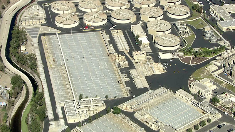
Carson treatment plant
“These tunnels come under the umbrella of ‘aging infrastructure,’ ” explained Haug. “They flow full every day and there is a capacity issue with them. Back in 1995 we had two extreme storms that came through the southwest and we reached our limit for the system. This, coupled with our knowledge of the active Palos Verdes Fault that both tunnels have to cross, made us realize we need to provide a more robust system.”
Part of the problem is that nobody knows for sure what condition the existing tunnels are in – they have never been inspected since their original construction, and nor can they ever be under the current configuration.
According to Haug, gaining access into the existing tunnels is extremely difficult. Neither tunnel can be taken out of service due to the quantity of effluent flow, and the physical layout of the system. The 12ft tunnel cannot be taken out of service at all because of the way it was built, and as a result of operating at full capacity it would be almost impossible to shut down the smaller diameter tunnel to enable inspection.
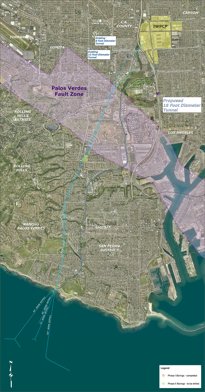
Fig 1. Alignment of 12ft and 8ft tunnels, and new 18ft tunnel
Haug further explained the Sanitation Districts do not have a reason to believe there are any restrictions within the existing tunnels. “Nonetheless we are relying on a system that is 75-plus years old and by the time this new tunnel is built, it’s going to be pushing close to 90 years old. The question becomes how reliable are the materials that were used to build the original tunnels, both of which were hand dug back in the day – we know a lot more about the concrete and rebar today than we did back then.”
Tunnel alignment
The new 18ft (5.5m) tunnel will start at the treatment plant in the City of Carson and end at the existing manifold structure at Royal Palms Beach for connection to the four ocean outfalls (Fig 1). The existing 12ft and 8ft tunnels follow a very direct alignment to the manifold structure, but the environmental documentation stipulates that the new tunnel must follow public rights of way as far as possible – hence its more serpentine route.
As a result of the hilly topography of the southern half of the alignment, where cover above the crown will be up to 450ft (137m) for an average depth of 300–350ft (91–107m), the tunnel is designed without any intermediate shafts. “Sinking an intermediate shaft within this section would have been very challenging” explained Haug.
The tunnel, therefore, will be serviced from a single launch shaft, sunk to a depth of approximately 100ft (30.5m) below grade. In the first half of the drive, up to about the 190,000ft (5.8km) mark, the TBM will be operating under relatively shallow cover of 60–70ft (18–21m). “We are expecting to go through two types of media – the northern part of the alignment is through the alluvium material, while the southern part features more rock-like material.”
Palos Verdes Fault
At the 85,000ft (2.6km) mark the TBM will enter the seismically active Palos Verdes (PV) Fault zone (Fig 2). Geophysical and geotechnical surveys have indicated a number of fault splays within the 75,000ft (2.3km) wide PV zone, and at these locations a 16ft (4.9m) diameter steel pipe, backfilled with grout, will be inserted within the segmentally lined primary lining.

Fig 2. The seismically Palos Verdes fault zone lies at the heart of the northern end of the alignment
“These pipes will be inserted in sections where we have determined the faults are located – for several hundred feet on either side of the splay,” said Haug. “In the event of an earthquake, the steel pipe inside the rigid concrete segmental lining will deform rather than rupture so that the flow can be maintained until the tunnel can be drained, shut off and repaired while effluent is diverted into the redundant system of the original 12ft and 8ft tunnels.” So far three locations for a steel pipe have been identified, but this is subject to review as a fuller picture emerges from the geotechnical investigation that is now drawing to a close.
TBM
The final diameter of the TBM is contingent upon final design of liner thickness – which is still being evaluated in a range between 12-15in (300–375mm) – implying a cutterhead size of approximately 21ft (6.4m) diameter.
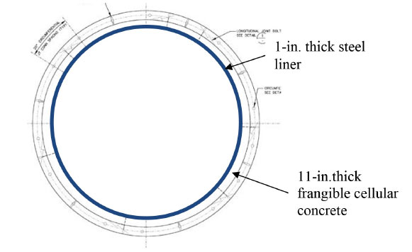
Typical cross section of 16ft i.d. steel liner
“During the design process the hydraulics of our system drove the decision to choose an 18ft i.d. tunnel,” explained Haug. “We did evaluate as low as 14ft (4.3m) and as great as 22ft (6.7m) but when we were looking at the different aspects of what we would gain hydraulically from each diameter, weighed against the cost of each, the sweet spot of 18ft came out: at 18ft we were getting the most bang for our buck.”
“Right now we are looking at allowing the contractor to specify what type of machine to utilize, and our environmental review takes account of both a slurry machine or an EPBM, though at this stage we don't know which way they [the contractor] will go with regard to machine selection.”
One element of the tunnel design that will certainly work in favour of the selected contractor is that the gradient is uphill – which will have the benefit of allowing any groundwater inflows to drain back behind the TBM towards the launch shaft back to the treatment plant. Such a design is actually intended to facilitate maintenance, and enable dewatering from the treatment plant side, rather than having to do this from the beach side. However, tunnelling uphill will afford the contractor extra control over water that permeates during the construction phase.
Primary lining
The main tunnel will feature a concrete segmental lining. “We are still working on the design,” explained Haug, “but right now we are looking at 12-15in (300–375mm) in thickness.” One of the unique aspects of the project is that the effluent, during certain flow scenarios, will have to be pumped out as opposed to flowing by gravity. At such times the tunnel will experience higher than usual internal pressures. These pressures are not as high as one would find in a water conveyance tunnel, explained Haug, but the internal pressure will place the liner into a tension situation.
Since the internal pressures within the tunnel will not be consistently high, fitting long sections of secondary steel pipe to carry what will be only an intermittently high-pressure load of up to 50 psi, would have placed unnecessary cost and schedule pressures on the program.
Post-tensioning in Switzerland
Construction in Switzerland in 2007-08 of the Thun Flood Protection Tunnel – designed to divert more than 100m3 (26,400 US gal) of water flow/min – called for a post-tensioning (PT) system that would be able to cope with static and dynamic pressure fluctuations from both within and without the segmental lining.
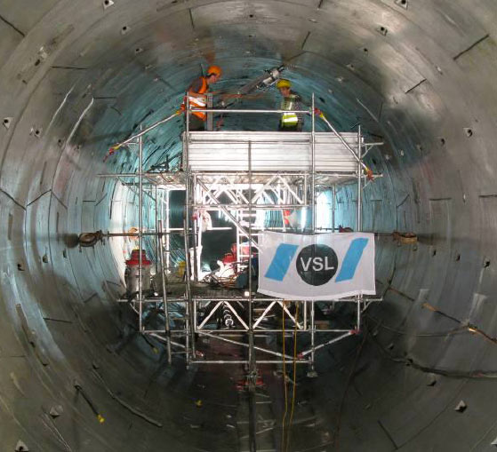
Working platform inside Thun Tunnel

Injection of the box-out
At a length of 1.2km (3,937ft) and with an i.d. of 5.4m (17ft 9in) – almost identical internal dimensions to those in Los Angeles – each ring of concrete segments of 1.2m (3ft 11in) x 300mm (12in) comprised five segments + key.
Pressures meant that tensile stresses would occur in the segmental ring, and VSL of Switzerland proposed a solution using the Z-anchorage system to give the benefit of continuous forces around the ring while minimizing the number of stressing pockets. Also proposed was the use of plastic ducts and 23mm (0.5in) steel monostrands in order to lessen the frictional losses along the tendon. All VSL’s proposals were accepted and two tensioning cables inside each ring were specified. After stressing, the visible box-outs (‘pockets’) were grouted with a special mortar normally used in geotechnical applications.
VSL was set, and hit, a tight three month target of installing all the PT tendons, stressing them, and grouting all the box-outs along the whole 1.2km length (1,000 rings) of the tunnel.
Post-tensioning (PT) concept
The concept is for a duct to be built into the manufacture of each and every segment, so that when the ring is assembled, a steel “tendon” can be run through it and tightened, or tensioned.
“There is a tensioning ‘pocket’ in one of the segments on each ring where a tendon can be fed into and through the duct within the ring,” said Haug. This steel tendon can then be tightened at the externally visible ‘pocket’ area of the ring, to the specified force required. “This will keep the liner locked in so it can handle the specified internal pressures [that will be experienced during pump out] without the risk of the segments falling apart.”
PT as a method of reinforcement is commonly used in bridge construction, and in the construction of large buildings, above-ground liquid holding tanks, and even nuclear power stations, but its application in the tunnel construction industry is still in its infancy. Before the Sanitation Districts proceed with the PT system a proof of concept demonstration is scheduled within the next few months to put the theory into practice. “We are going to fabricate some rings and pressurize the system to make sure we can achieve the design pressure of the tunnel during the anticipated future flows. We will be doing this as full scale as possible by using some existing moulds that are similar in diameter. We haven’t finalized the contract for this testing yet, but we expect to carry out the demonstration over four rings of length,” said Haug.

Fig 3. Post-tensioning tunnel lining concept

Stressing jack tendon tensioning
If the system is adopted it is likely that the segmental lining for the whole of the northern section – that is, through the softer water-bearing alluvium geology – will be constructed in this way. “We would definitely adopt PT for this section,” said Haug. The rationale is less to do with the seismic threat (which is being managed via steel liners through the fault splays) and more to do with the need to mitigate the possibility of effluent leakage between gaps that may form between segments in those sections of the alignment where the softer and more highly groundwater-bearing soils are less likely to be able to resist the high internal pressures within the tunnel during pump-out scenarios.
The Sanitation Districts also evaluated different lining methods to handle the pressures. Two pass systems, such as installing a steel pipe throughout the entire tunnel, or a secondary cast-in-place liner were investigated. However, for the increased cost and extra construction time that those systems would add to the project, it was determined that post-tensioning was the optimal system. In the Swiss water diversion tunnel at Thun, 1,000 rings of slightly smaller diameter were tensioned in a three-month period, and work is likely to be able to proceed simultaneously behind the TBM advance.
Treatment plant and outfall structures
The project is expected to go to bid towards the end of 2016. “Once we advertise and bid, we expect construction to last 7.5–8 years as an initial assessment,” said Haug. “But the tunnel is the critical path – this must be constructed and finished before work can start on some of the other structures that we will also have to complete as part of the process of diverting the flow. We have structures at our treatment plant, and we will need to demolish the existing manifold structure down at the beach and build a new one – what complicates things is that both of these are being built around an active system.”
RETC Technical Presentation

David Haug
Sanitation Districts Senior Engineer David Haug and the design team behind the LA Outfall Tunnel Project will be presenting a technical session entitled Digging to the beach: The final design of the JWPCP effluent outfall tunnel project in the Future Projects category of lectures at the RETC in New Orleans on Tuesday 9 June.
The session – which includes prior presentations on the Albany Park Stormwater Diversion Tunnel (Chicago), New York City’s water bypass tunnel, and the Bay Delta Tunnels project (Northern California) - starts at 8.30am. Co-presenters for the LA project are D. Yankovich and J. Kaneshiro of Parsons and S. Dubnewych of McMillen Jacobs Associates.
At the treatment plant there is a 14ft (4.3m) semi-elliptical force main that the tunnel will have to tie into; this will require the contractor to cut out a section of the force main under live conditions to divert the flow into the 18ft tunnel. Meanwhile, down at the manifold structure on the beach, both of the main outfalls will have to remain in service at all times even as the new connection is made. “The sequencing of flow diversions under live conditions is one of the major challenges of this project,” said Haug.
Procurement and schedule
The project is currently being advanced as a single contract, the rationale being that when it comes to the sequencing of construction – and the precise timing that will be needed for the switching of flows at both ends – to do otherwise would be to create a potential “scheduling nightmare” should one contractor fall behind. “Using a single contractor mitigates this risk,” said Haug.
“If we stay to our schedule the project will go out to bid very late 2016 or in the first part of 2017, after which it would take a month or two to finalize contract and move to the NTP – so I would say early construction could start towards the end of 2017 or early 2018.”
|
|
|
|
|
Add your comment
- Thank you for taking the time to share your thoughts and comments. You share in the wider tunnelling community, so please keep your comments smart and civil. Don't attack other readers personally, and keep your language professional.