Innovations for the Fehmarnbelt tunnel option
May 2010
S. Lykke, Project Director, Tunnel, Femern Bælt A/S and W.P.S. Janssen, Sr. Project Manager, (Tunnel Engineering Consultants, Nijmegen, The Netherlands) for the Rambøll-Arup-TEC JV
-
In September 2008, the Danish and German Ministers of Transport signed a treaty1 to establish a link across the Fehmarnbelt between Lolland, Denmark and Fehmarn, Germany. The same treaty was subsequently approved by the Danish Parliament and the German Bundestag. The Fehmarnbelt Fixed Link will be the third major crossing in Denmark after the realization of the Great Belt (1998) and the Øresund (2000) links. It represents the missing link in an efficient transport corridor between Scandinavia and Europe and will accommodate a four-lane motorway and a double track railway.
-

Fig 1. Femern Fixed Link
- Denmark has assumed sole responsibility for the financing, implementation and future operation of the fixed road and rail link across the Fehmarn Strait to Germany and for this purpose the state owned organization Femern A/S has been established. A feasibility study2 performed in 1996 - 1999 looked into a great number of possible solutions, including bridge and tunnel (immersed and bored) options, train shuttles, double and four lane motorways, single and double track rail integrated or seperated from the motorway. On the basis of the study it was decided to construct a four-lane motorway and a double track railway. A cable-stayed bridge was favoured and the Danish and German governments labelled this as the preferred solution. However, it was also decided that an alternative solution in the form of an immersed tube tunnel for the entire crossing had to be investigated during the planning stage. Variants which combine in line or parallel bridge-tunnel combinations are not considered due to the great waterdepth, which would require a huge reclamation to connect the bridge and tunnel for the in line option, and for economical reasons for the parallel arrangement. The crossing will be either a bridge or a tunnel and the decision will be taken only after it has become clear that both options are technical feasible and necessary approvals can be obtained.
- In April 2009, Femern A/S selected the Rambøll-Arup-TEC Joint Venture Fehmarn Belt Link for the design of the tunnel alternative.
- The immersed tunnel solution will set new records in terms of its dimensions; it will be the longest tunnel and one of the deepest tunnels of this type ever built with a length of 20km and foundation depths reaching more than 40m under the sea surface. The size of the project will create major challenges for designers and future contractors and will allow for an innovative approach based on proven technology. During the design phase the competition between the bridge and the tunnel solutions will be amongst the main drivers for this process. The obvious advantages of a tunnel solution in terms of navigational risk and visual impact have to be balanced with the obvious disadvantages of higher cost and extended safety measures required due to its length.
- If constructed, the immersed tunnel, would go directly into the Guiness Book of Records. As well as being the world's longest immersed tunnel, it will be the world's longest combined road and rail tunnel; the world's longest under water tunnel for road; the deepest immersed tunnel with road and rail traffic; and the second deepest concrete immersed tunnel. The size of the project is about five times the tunnel part of the Øresund Link between Denmark and Sweden, currently the longest immersed concrete tunnel and will require a huge logistical and qualitative challenge to build in the available construction time of approximately six years. The amount of material to be dredged for the trench is about 20 million m3 and the amount of concrete for the immersed tube elements is about 3 million m3. Production of the elements would require four to five construction facilities as used for the Øresund link.
- Operational safety in a tunnel of this length is a challenge and requires careful considered and a high level of self rescue options for users. The combination of the road and rail tubes in one cross section is an advantage in this respect as transverse escape to a number of safe non-incident tubes is possible. User safety will not only affect the design but is an important issue in the approval process and public acceptance of the tunnel solution.
- The agreement Treaty defines a crossing between Puttgarden and Rødbyhavn within a corridor of some kilometres of width around the existing ferry line. During the design process a great number of options for the alignment in this corridor have been investigated. A potential alignment near east of both harbors allows an alignment close to the existing infrastructure corridor with low impact and does not interfere with the existing communities of Puttgarden and Rødby. The selected cross sectional arrangement of the two road and rail tubes side by side with the road west and the railway east coincide with the arrangement on the existing infrastructure and requires no weaving to connect. The dredged material from the trench will most likely be disposed on both sides off shore. The portal and ramps structures are planned to be constructed in these reclaimed areas. They are intended to have a natural appearance and are supposed to become an area of natural beauty. The immersed section of the tunnel, with a length of about 18.5km, connects the two portal buildings at either side.
- Immersed tunnel section
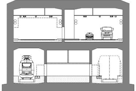
The immersed section of the link represents more than 90% of the total length of the crossing and is the main driver for the project cost. As a result, paramount attention has been given to the development of the immersed tunnel cross section. The emphasis has been on reducing the construction time and optimizing the required internal space while maintaining an adequate safety level and self rescue ability for the users. - Based on minimum functional requirements, such as the traffic envelope and the basic space requirements for installations, a wide range of options for the cross section have been listed and evaluated applying multi-criteria analysis to compare aspects such as cost, safety, construction time, constructability and operation and maintenance. A first evaluation has been based mainly on qualitative aspects and experience gained during the construction of similar projects including the Øresund Fixed Link in Denmark, the Bosphorus Crossing in Istanbul3, and the Busan Geoje Link4 in South Korea.
- The generated cross sections can be divided into three arrangements;
-
• Sections which combine rail and road in one level with the objective to concentrate material and functions.
• Sections which combine rail and road in two levels to allow for a combined use of ventilation ducts and galleries for rail and road.
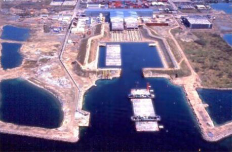
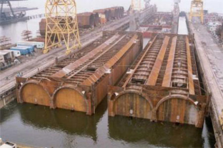
• Separate tunnels for rail and road with the objective to allow for separate alignments and independent construction. - In addition to these arrangements three different structural concepts and/or construction methods have been considered (i) reinforced concrete constructed traditionally or by full sectional casting (ii) modified singular steel shell sections and (iii) steel concrete composite sections.
Fig 3. Construction methods / Structural concepts: Øresund production facility – Casting basin – Double steel shell
- A quick assessment showed that the two level arrangements did not have real potential to generate sufficient added value because the sections complicate construction and extend the production time since for this cross section full sectional casting is not an option. The tall cross section also requires deeper dredging, a deeper casting basin, and deeper and longer access channel to the potential casting basin areas. The combined use of centrally placed ventilation ducts and galleries did not compensate for the extra cost involved.
- The option of having separate alignments for road and rail is more costly but creates more flexibility with regard to design and construction. For example, separate tunnels have the advantage that the rail tunnel alignment is not constrained with respect to the road alignment and visa versa. However, the impact on land will most likely increase by having two different alignments. Another important drawback is related to safety as combined use of safety provisions in rail and road tubes is not possible. The construction of the rail and road tunnel elements for separate tunnels is well within proven technology, as is full sectional casting. These provide a better allowance for a geographical spread of the construction facilities, which may reduce construction and planning risks and stimulate competition.
- The one level arrangement has been identified as having the best potential for final optimisation as the various arrangements of rail and road tubes in this one level layout allows for an effective use of the road tubes in case of an accident in the rail tube and vice versa. Furthermore it is expected that the combination of rail and road tunnel in one level cross section will result in synergy during construction, transport and immersion. In addition, the dredging depth can be minimised.
- From the palette of the one level sections, the arrangement with the rail tubes at the outside was initially favoured but was abandoned due to the impact of the space requirements for the installations. Space for the necessary transformers is created by implementing special wider elements every 1,800m. Apart from space for the transformers these special elements provide space for pump rooms, parking lay-bys for maintenance staff, ventilation niches in the roof and other operational and maintenance facilities. The intention has been to concentrate all diversions from the standard element in these special units. The pre-condition to keep the road tubes next to each other for safety and operational reasons and the demand to have access from the road to the transformer rooms abandoned the use of a cross section arrangement with the rail tubes at the outside.
-

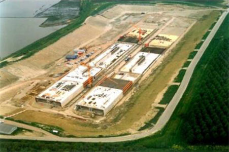
Fig 5. 4-line casting facility
-
Construction of the elements
The construction of the elements will be a massive operation in which an element will be delivered to site for sinking into position every second week. In order to achieve this within the given time frame of about 2.5 years for the construction of the elements, a number of production facilities are needed.The length of the tunnel calls for an industrialized production process similar to that used for the Øresund Link. A high production rate at peak of about two 180m long elements in two months turned out to be realistic at the Øresund. The production under controlled ambient conditions proved to be beneficial for the quality of the concrete which is essential as the application of an external membrane is not foreseen. For this reason it is anticipated that construction of the 80 standard elements with a length of 200m each will take place in two production facilities with four and five production lines respectively. The special elements are shorter than the standard elements but more complicated, so it is expected that these will be constructed in a casting basin using full sectional casting to prevent hydration cracking and assure adequate quality. -
Safety, rescue and ventilation
The Fehmarn Belt Tunnel has a number of characteristics which impact on the safety and rescue strategy and the design of ventilation systems. The biggest challenge is the tunnel's length of approximately 19km under water. With little scope for egress or access points except at the portals, evacuation from one tube to another tube combined with efficient management procedures for evacuation towards the portals is paramount. Furthermore, the ventilation system must be capable of transporting air or smoke over long distances and overcome large pressure losses. The accumulation of emissions from road traffic over the tunnel length will be an issue of priority and fresh air provisions not just through the portals but also at intermediate points are being considered. - The ventilation system design and the escape route provision have a major impact on the cross sectional area, which, for an immersed tunnel, has significant construction and cost implications. However, the combination of rail and road tubes provides a number of opportunities for functional sharing of resources and installations leading to a more efficient solution.
- The different proposed tunnel cross sections are at concept stage assessed according to criteria set up for escape and fire fighting respectively.
-
Assessment of means of escape:
• General evacuation strategy (where do you go?)
• Escape route conditions (how safe is it going there?)
• Places of relative safety (how safe are you when you got there?)
• Non-fire hazards (which other hazards are present – besides heat and smoke?)
-

Fig 6. Self–rescue
-
Self-evacuation shall generally be through cross passage doors from the incident tube into an adjacent non-incident tube. Self-evacuation along the length of the tunnel is a possibility but not convenient due to the potential distances from a fire incident to the portals (see Fig. 6 "Self-rescue"). Assessment of the fire fighting will include:
• Fire fighting access routes
• Access route conditions
• Equipment and resources - Fire fighting shall generally commence from an adjacent non-incident tube. Early detection and early suppression via remote controlled permanent systems provide a relatively safe environment from where the fire service can establish a bridgehead and commence operations. In many of the conceptual designs the fire service can use the road tunnel to tackle a fire in the rail tunnel, which allows for less onerous access conditions.
-
Comprehensive analyses are being made in order to identify which of the following issues are decisive for designing the ventilation system:
• NO2-concentration
• Other emissions
• Visibility (dust concentration)
• Smoke control - The analyses undertaken to determine the decisive parameter is made complicated by the fact that many of the parameters in the calculations are estimated based on past experience or future expectations. The traffic volume, the vehicle emission factors, the NO2/NOx-conversion factor and the acceptable threshold values are all subject to significant and global debate. The situation is aggravated further by considering scenarios up to 20 years into the future when both the transportation patterns and vehicle traction technology may differ significantly from what we know today. Fig 7 shows a projection of the total exhaust pipe emissions in the road tubes in the period 2018-2030. As can be seen, significant reductions in the emissions are expected even though the traffic volume is modelled to increase by 2.5% per annum.
-

Fig 7. Exhaust pipe emissions
- Although the projections for traffic volume indicate an increase over the years, the overall traffic volume is relatively low when compared to a city centre tunnel. The relatively low traffic volume suggests that congestion will not be a regular occurrence and this eases some of the requirements on the ventilation system under day-to-day conditions. The ventilation capacity needed in the event of a fire for smoke control and smoke clearance depends highly on the anticipated fire size. Appropriate design fire sizes for rail and road vehicles are heavily debated and vary significantly depending on a number of factors including the impact of passenger and freight trains and whether these trains are diesel or electrically driven in the rail tunnel. All such factors are being evaluated for the purpose of defining the resulting design loads for the future scenarios.
-
Dredging
The construction of a fixed link across the Fehmarnbelt will pose major dredging challenges in terms of the water depth, the varying types of soils, the strict environmental control and the need to meet tight construction schedules. - The dredging and reclamation works include backfilling the trench after installing the immersed tunnel and the creation of land/marine disposal areas. Further dredging works will be required for sourcing marine sand for backfill and the potential creation of casting basins for fabrication of tunnel elements.
- Dredging for the immersed tunnel solution will produce a trench some 40-50m wide x 12-15m deep. These parametres give a total of some 20 million m3 of soils to be dredged. The maximum dredging depth is some -45m at the centre of the Fehmarn Belt, but most large sized pieces of conventional dredging equipment can only dredge to a depth of some -25m. Dredging beyond -25m will likely have to be performed by grab dredgers and trailing suction hopper dredgers.
-
-ART.jpg?v=4b39b50af0d88ba738bdfc27a08f33b230294d85)
Fig 8. Backhoe dredger
- The soils to be excavated from the tunnel trench will vary from sands/silts to stiff and very hard clay-till with boulders. Mechanical dredging of clay materials in the nearshore areas by backhoe dredgers and grab dredgers will provide construction material for the perimeter bunds of shoreline disposal areas and for the rehabilitation of coastal dikes. Mechanical dredging can also be performed throughout the length of the trench with or without the assistance of hydraulic dredgers. Unsuitable material may likely be placed in shoreline deposits and some in marine disposal areas.
- Re-use of as much as possible of the dredged materials in a beneficial way must be considered because the disposal of such large quantities of soil into the marine environment may prove to be unacceptable. While an obvious use for the dredged material will be the backfilling of the trench, it will only account for a part of the material dredged.
- Dredged material which cannot be used for backfilling the trench can be used to create wetlands in front of the existing coastline. Surplus of dredged material could be deposited in one or more marine disposals, but only after having met the necessary environmental regulations.
- Two work harbours will be constructed within the planned shoreline disposal areas for transport of personnel, to provide a safe haven for marine construction equipment and to provide facilities for supply, stockpiling and load-out of materials and equipment. These work harbours will have a water depth of -7m and will be used throughout the construction period. If correctly planned, such harbours could be converted into small marinas on completion of the works.
- Once the trench has been dredged the foundation bed for the immersed tunnel elements will be placed using sand or gravel delivered via pipes cast into the tunnel element or from a drop-pipe installation on a scrading pontoon.
-

Fig 9. Scrading pontoon
- When a section of tunnel elements have been immersed and connected, they can be backfilled by locking-fill (gravel), general-fill (sand and engineered fill from excavations) and protection layer (rock or sand/gravel). The protection layer will protect the tunnel in the event ships dropping or dragging their anchors over the tunnel or in the event a ship sinks on the tunnel.
- The Fehmarnbelt Fixed Link is a unique project and the design and construction of the associated dredging and reclamation works for both the bridge and immersed tunnel solutions will raise many new challenges. Conventional dredging equipment and techniques will be able to deal with many of the challenges the project has to offer, but will have difficulty dealing with the dredging of stiff and very hard materials at depths exceeding -30m and reaching a maximum dredging depth up to -45m. Serious consideration needs to be given to modifying existing equipment or producing custom-built equipment and to developing innovative techniques to deal with all the cutting edge project requirements and challenges including limiting effects on the environment during the periods in which dredging and reclamation will take place.
- The process of developing suitable and innovative tunnel and bridge designs for the Fehmarnbelt Fixed Link up to a level at which approval can be obtained is exceptional and illustrates the determination of Femern A/S to establish a state-of-the-art crossing of the Strait ready for efficient commercial operation not later than 2018. The design of these options is well on its way. It is expected that it will take up to ultimo year 2010 before a clear picture of the potential best solution has been established. Until then the Fixed Link solution will be either a bridge or a tunnel.
-
1. Denmark Misinstry of Transportation
2. Femern Fix Link Project
3. Bosphorus Crossing, Turkey
4. Geoje Fixed Link, South Korea
This paper was prepared for, and presented at the ITA World Tunnel Congress in Vancouver in May 2010 -
Femern Bælt fixed link options - TunnelTalk, June 2009
|
|
|
|
|
Add your comment
- Thank you for taking the time to share your thoughts and comments. You share in the wider tunnelling community, so please keep your comments smart and civil. Don't attack other readers personally, and keep your language professional.


