Concrete lining: Maximising the advantage
Dec 2004
Shani Wallis, Editor
-
Applying a more industrialised, production-line approach to long distance tunnel construction takes another step forward with design and application of two self-propelling workstations currently employed on the longest headings of the St Gotthard Baseline railway project in Switzerland.
- Powerful gripper TBMs come into their own on long rock drives where their potential speed of advance provides distinct advantages over the alternatives. The disadvantages of the single face of attack however remain. One of the greatest disadvantages is waiting for hole through of excavation before working a second and third pass to install finishing works. This can add years to the project programme - unless these works can be incorporated as concurrent operations.
- Incorporating finishing works with excavation is not a new idea. Precast concrete segments for example are often incorporated on rock TBM drives to provide the final lining concurrent with tunnel advance, the annulus filled with pea-gravel and back-grouted(1). On the UK side of the Channel Tunnel an expanded (non-bolted) precast concrete segmental lining was installed directly against the competent chalk marl, with 20mm pads cast onto the extrados providing initial ground contract and an annulus for subsequent grouting. For the project’s two 17km+ UK marine running tunnels, ring build was simultaneous with gripper TBM excavation and most of the six TBMs used on the UK side had innovative double segment erector systems to accelerate the speed of ring build to keep pace with TBM advance(2). There has also been development and application of the extruded concrete lining behind shielded TBMs. The drives under the Rhône and Soane Rivers for the Lyon Metro in France in the late 1980s are one example(3).
- In addition to these systems there have also been many applications of in-situ concrete lining being cast as separate operations behind tunnel advance. Depending on the size of the tunnel, the degree of finishing works, and the methods of servicing the excavation, the cost effectiveness of these concurrent operations has been debatable. There is also the question of safety for workers on these intermediate stations, as well as the priority for maintaining services through the workstations to the excavation heading.
- Advent of the long TBM headings required for the AlpTransit Baseline Railway tunnels in Switzerland focused attention once again on the need to optimise the tunnelling process. Single long distances heading were unavoidable under the massive overburden of the Alps, and the need to bring all the separate sections of tunnel to a near simultaneous conclusion and within the shortest feasible construction period was essential to the viability of the projects. Taking years to excavate the longest of the headings and then taking years again to complete the finishing works was threatening project feasibility. To address the issue, the planners and designers of the long St Gottard project headings specified that the final in-situ concrete lining had to be cast concurrent with TBM excavation.
-

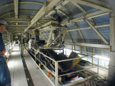
Wurm walkway
- The Consorzio TAT (Tunnel AlpTransit-Ticino), working from the south of the St Gotthard project from Bodio, has invested most in solving the issue. Comprising Zschokke Locher, Hochtief, Alpine Mayreder, CSC Impresa Construzioni, and Impregilo, the Consortium won the two longest contracts for the twin-tunnel project - the 16.6km long Bodio section and the 15.1km long Faido section. “In total, this 31.7km of twin 8.8m o.d. tunnel, plus access adits, cross passages, and the caverns of the multi-function operating facility at Faido amounts to more than 4 million m3 (10.6 million tonne) of excavated material,” said Bruno Gugelmann, Poject Manager for TAT. “We were awarded both contracts in June 2001 and our contract end is in 2011. We bid the two contracts separately and also offered a combined bid to present the owner the benefit of economic savings. In our combined bid we proposed using the same two TBMs for both contracts starting at Bodio and continuing into the Faido headings. Two extra TBMs would have been required had the contract been awarded to a different contractor. In the same way, the systems we were proposing for concurrent installation of the finishing works would also follow on into the Faido section, adding again to combined contract cost effectiveness.”
- In January and February 2003, the Consortium launched its two 8.8m o.d. Herrenknecht rock TBMs from an assembly chamber some 1,580m in from the Bodio portals in the west tunnel and 2,540m in on the east tunnel. The lengths back to the portals have been excavated by drill+blast and a bypass tunnel (completed under an advanced works contract) provided early access to the TBM assembly chamber.
- Plans for concurrent installation of the final lining began in the early tender stage. “As well as a contract requirement, we too could see that there was no way to separate the two passes (excavation and lining) and still meet programme,” said Gugelmann. “We had to design a self propelling bridge or gantry working station off which we could perform all the necessary finishing works while maintaining operation of the services and supply trains to the TBMs.”
- To work with them on the design, TAT engaged a joint venture of Bernold-Ceresola AG of Switzerland and Maschinen-und Stahlbau Dresden (MSD) Germany both of which are part of the Herrenknecht Group.
- The starting point for design was the final lining specification. As part of the TBM operation, a permanent in-situ concrete invert is cast and primary support of rockbolts, wire mesh, shotcrete and steel arches as required is installed. On the in-situ concrete base slab, the permanent track bed will be cast as part of the separate track-laying contract. In the interim, the rail tracks for the construction works are laid.
- For the final works, the design specifies a minimum 250mm thick in-situ concrete lining and a systematic waterproofing membrane over the arch and into concrete drainage pipes either side of the invert slab. In addition, finishing works include installation of any supplemental primary support (extra rockbolts or wire mesh, or more shotcrete) and re-profiling of any tunnel deformation or overbreak to ensure a minimum 250mm lining and a smooth surface for application of the waterproofing membrane. The in-situ concrete lining is largely un-reinforced with reinforcement applied only in specific zones and at cross passage junctions. Cross passages are at 312m intervals and their drill+blast excavation is also concurrent with tunnel advance.
-
‘Wurm’ design
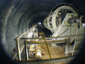
“To comply with programme, we needed to achieve a minimum 20m average of finished lining/day/tunnel,” explained Gugelmann. In final design of the workstations this was increased to 24m of cast concrete/day using two 12m long shutters. “Longer than that would increase the probability of stress cracking in the mass concrete or require reinforcing to avoid these cracks, and cause co-ordination problems in the chain of operations.” - When all was considered and agreed, each workstation or ‘worm’ as they have been named (“Wurm” in German), is 600m long and weighs about 1,900t! Each comprises 34 trailing gantries and accommodates 12 different work operations. The string of linked gantries is divided in the middle at station 17 with a set of four clamps that engage, each pair in succession, on the support rails of the gantries (installed initially to support the trailing backups of the advancing TBMs) to push and pull the 600m long workstations through a 3m stroke of hydraulic rams much like a caterpillar or worm.
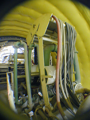
- This 3m incremental movement operates within a second system of advance that moves in 150m lengths. At each end of the long workstation is a separate gantry on which are fitted a 150m payout of 200mm diameter water hoses. These gantries remain stationary during the shorter increments of advance, paying out the service lines at the back and reeling them in at the front as interim workstation gantries advance. Cable reel with am 800m payout of 24kV high voltage electricity cable and communications cables are installed on the first and last gantry of the Worm.
- The 150m of advance corresponds to a week’s advance of the workstations, producing 24m of finished concrete lining/day, 6days/week and using the seventh day to disconnect and reconnect the TBM service lines and reset the workstation. “Once reset, there is six days of uninterrupted TBM advance and another 150m of finished tunnel to produce,” said Gugelmann.
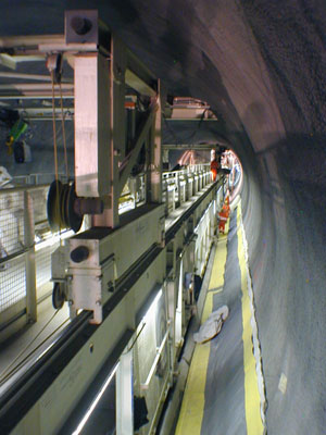
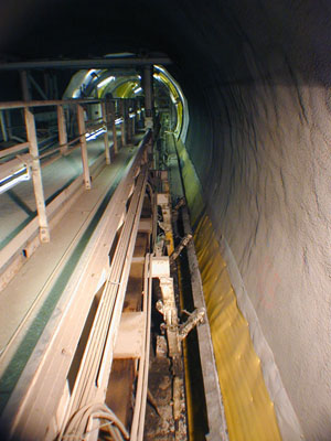
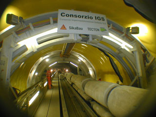
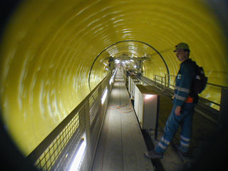
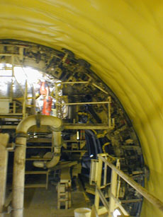
- After seeing an illustration and video presentation of the Worms on the Bernold-Ceresola stand at the 2004 BAUMA exhibition in Munich, TunnelTalk organised a visit to see them in action at Bodio in October. The striking impression is the efficient incorporation of all the different operations on the working platforms and also the safety measures incorporated to minimise risk to workers. The working environment of the platforms is completely and effectively caged off from the tracks of through-train traffic; there is a high level of lighting at each workstation; hand rails and guards at all walkways, ladders and openings in the decks; three safety refuge cabins for workers at strategic points on the working deck; and a local ventilation system at the reprofiling and shotcreting station to control dust and temperature.
- Details of the 34 gantries of the two Worms that will complete about 25km of final concrete lining over the next five years from the Bodio portals for the Consorzio TAT.
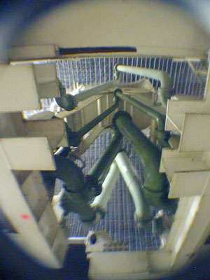
- Starting from the front, the sequence of operations on the Worms is as follows: Gantry 0 a, b, c – hose reel and stations to take the two TBM water supply pipes off the tunnel wall. Water has already been bypassed at the leading hose reel gantry. Cooling water is supplied to the TBMs at 3,000litres/min and under 25bar pressure. Water pipes to the Worm are 300mm diameter, and 200mm diameter from the Worm to the TBM. Valves every 300m minimise water loss and allow for disconnecting and reconnecting the water lines. The electricity and communications cables have also been re-routed off the tunnel wall onto the Worm.
- Gantries 1 a, b, c – ventilation system, working and safety containers
-
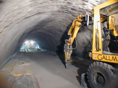
Gantries 2 a, d, c– reproofing of the tunnel profile as necessary using an excavator fitted with a hydraulic hammer
Gantry 3 – the shotcreting station fitted with Sika wet-mix shotcreting pumps and a nozzle mounted on a mobile ring beam.
Gantry 4, 5, 6, 7 – tunnel cleaning works including a vacuum system to lift rebound and debris off the invert either side. - Gantries 8, 9 – install the waterproofing membrane and drainage pipes, set the formwork for casting the lower part of the concrete lining each side of the invert.
-
Gantries 10 a, b – shutter for the lower concrete cast.
-
Gantries 11, 12, 13, 14 – climate control cover for curing period of the lower concrete cast and install the waterproofing membrane supplied by SIKA and in 4m wide rolls. These are fitted to a carriage that unrolls the material and attaches it to plastic fixings nailed to the tunnel wall and through the fleece. As the carriage travels the ring beam from one side to the other, rollers keep the membrane taught and press home the material to the valcro fixings. Off the same gantries, the membrane is heat welded at the circle joint and to the longitudinal overlap to the culvert membrane. The waterproofing station was designed by Rowa and built onto the gantries supplied by Bernold-Ceresola/MSD JV.
Gantries 15, 16 – station for installing the necessary reinforcement and casting the concrete at cross passage junctions. Using the Worm’s special shutter, the first 1.5m of the cross passage is lined. The remainder is cast as a separate finishing operation.
- Bridge 17 – the 3m-stroke propulsion system.
- Gantry 18 – the first 12m long arch shutter and concrete distributor.
- Gantry 19 – a curing canopy that maintains a controlled humidity and temperature for correct curing of the concrete once the shutter is struck.
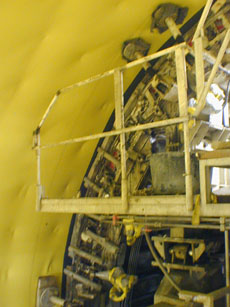
- Gantry 20 – the second 12m long arch shutter and concrete distributor. The two shutters work in tandem, Gantry 18 casting the leaders and Gantry 20 casting the infills. Stop-ends are required at both ends of the leading shutter. These need careful application to avoid damaging the waterproofing membrane. Concrete is transported from the concrete batching plant, operated under a subcontract at the Bodio portal site, via Mühlhäuser agitator cars and a single Schwing pump, stationed on the working deck delivers concrete via a manifold to fill both shutters.
- Gantries 21, 22, 23, 24, 25 – further curing canopies. The environment behind the canopy is monitored and conditions adjusted automatically to maintain a humidity of 95% and a constant temperature of 30-40ºC. These curing canopies provide at least three days of controlled curing.
- Gantries 26 a, b, c – replace the services back on the tunnel wall, now finished with its waterproofed in-situ concrete lining. Finally, reel in the 150m of hose extensions onto Gantry 26c and reset the Worm ready for the next 150m advance.
- To reset the Worm at the end of every 150m length, the services are disconnected and the TBM interrupted for at most 2.5 hours. This occurs 1 day/week at most and is co-ordinated to coincide with TBM maintenance downtime. Transporting concrete to the Worm for each daily pour is also co-ordinated to coincide with TBM downtime when train traffic to the TBMs is lighter and batching plant production can be dedicated to the lining operation. All electricity is supplied from the Switzerland’s national grid. Emergency generators are on stand-by for pumps, lights and ventilation while two emergency generators on the Worms would supply power to finish each pour should grid power fail mid-pour. Each Worm comprises about 50km of its own operating cable.
- During the 24h working day of three 8h shifts/day, it takes one shift to strike and prepare the forms and move the Worm forward (taking about 30 minutes to move 12m through the central 3m-push-pull propulsion system); another to complete the next concrete pour; and another 8-10h of curing, during which time maintenance is undertaken. At the same time, work at the other operation stations continues in order to keep pace with the casting programme. There are about 45 workers on each Worm/day, 20 in each full production shift and 5-6 in the maintenance shift.
- “At present the Worms are working five days/week for a maximum advance of 120m/week,” said Gugelmann. “The TBMs are operating 24h/day, 7 days/week and advancing at the moment at an average of about 20m/day or 140m/week.” When TunnelTalk visited the site in October, the two TBMs were about 7.5km into the 16km long Bodio tunnels. The west tunnel Worm was about 1,100m into its journey having started concreting from the TBM assembly chamber at the end of May 2004 while the east tube Worm had completed 250m after starting in mid-September. “We can increase the operation of the Worms to 7 days/week but we would always want a distance of about 2km between the TBMs and the Worms,” said Peter Vorwerk, tunnel manager for the Consortium.
- “This is needed for several reasons. First the excavated rock needs time to relax before the tunnel is re-profiled and the final lining installed. Steel arch deformation of up to 10cm due to stress deformation in the tunnel is not uncommon. Next, the distance is needed to provide for the California switch about 1km behind the TBMs. Twin rail tracks were needed through the length of the tunnels to accommodate concurrent lining and cross passage excavation. At the Worms and during the concrete pumping cycle, one track is dedicated to the concrete supply trains and the other for through traffic to the TBMs and the cross passage works. Finally, it is essential for the ventilation system.”
-

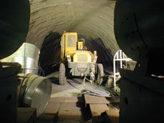
Gantry 20 Concrete distributor
- Ventilation in these long headings is critical, both to supply fresh air and to control the rising ambient temperature. Carrying a vent duct for forced ventilation from the tunnel portals was not viable and would have caused added complications at the concurrent lining operations. Instead the two main tunnel tubes and the cross-passages are the principal vent ducts. For the system to operate, a minimum two 40m long centre-to-centre cross passages must be open behind the TBM to connect the two headings and all those behind must be closed off. Fresh air is then drawn in via the east tunnel, and is picked up by the 2.2m diameter vent duct extending some 2km behind the TBMs to deliver fresh air forward to the TBM working area and directed it via one open cross passage to the west tunnel TBM heading. Exhaust air is drawn out via the second cross passage and expelled along the west tunnel all the way to the portal.
- The effectiveness of the system was apparent during the visit to the Worms. Fresh air drawn in from the portal was holding the temperature in the east tunnel several degrees lower then the environment in the warmer exhaust airflow in the west tunnel. Under contract specifications, the working environment at the TBMs and on the Worms must be maintained at a maximum 28ºC dry air temperature and slightly higher for more humid conditions. Airflow ventilation and heat-exchange cooling systems maintain these conditions.
- According to programme, the two TBMs are scheduled to break through into the Faido multi-function station caverns in Summer 2006. Following that the 16.6km finished west tube of the Bodio section is due to be handed over to the track laying and system fitting contractors in 2008. The finished east tube will be retained by TAT during excavation of the 15km long Faido tunnels to provide service train access back to Bodio. All muck from the Faido tunnels must be carried back to Bodio for disposal and all concrete aggregates, and perhaps also concrete, into them from Bodio.
-
Progress to date
When TunnelTalk visited in October 2004, the two Worms were still in the learning curve. “Our best progress to date on the west Worm is five pours or 120m/week,” said Gugelmann. “We still need to work on optimising the number of workers per crew, the sequence of work and the jobs/day. In addition we are having to undertake more reprofiling than expected and install more zones of reinforced concrete than anticipated. Squeezing deformation and some thicker layers of primary shotcrete need reprofiling and there are more zones being specified by the engineers for reinforced lining.
-

Gantires 21-25 Curing canopies
- In these reinforced zones polypropylene fibre is needed in the concrete mix to protect against fire-induced spalling and this takes longer to set before striking the forms. These changes to the original development sequences need to be incorporated into the optimum operation of each Wurm.”
- Behind the Worms the tunnels need further attention to install a walkway down both walls of each tunnel and through the cross-passages. This was not included on the Worms to avoid any damage during the on-going construction phases. A separate working platform or “Wurmino” has been designed to cast the lining for in the assembly caverns of the TBMs and the drill+blast tunnels back to the two portals.
- During discussions at site, it was agreed that combining all works either on one ‘Worm’ or trying to incorporate all operations on a long TBM trailing backup was not feasibly. This would be too complicated and would defeat the objective. “The overall aim is to introduce a more industrialised approach to tunnel construction,” said Bertram Liebler, a director of Herrenknecht and CEO of Bernold-Ceresola. Liebler has a background also in the auto production industry and continued: “It is remarkable to see how much streamlining could be achieved in tunnelling to minimise man hours and reduce labour requirements. Combining operations on the same programme or assemble line, such as casting the lining concurrent with excavation, is one example, but taking the idea to the next level of opportunity would require more standardisation in the industry. The fact that every TBM tunnel, for example, is different in diameter by perhaps just millimetres, and that every tunnel has its own individual lining design defeats even the start of a more stream-lined approach – an approach that could provide substantial economic savings, as has been demonstrated already in other manufacturing and construction industries.”
- The discussion continued to compare the prospect for the Bodio and Faido contracts had not the Worms been developed and applied. “To complete the two contracts within the contract period using a second pass for the lining we would have needed something like three continuous pour telescopic shutters of 300m long in each tunnel working simultaneously,” said Gugelmann. “As it is, the two Wurms are equivalent in cost to another TBM and headings of this length (30km+ each) are needed to optimise the investment.
-

Gantry 26 Final cable reels
- Having the task to design again, we would provide for a system to allow more flexibility or independence between the different operations and may try to retrofit such a system to get the best from these Wurms as they progress. We are also looking at perhaps prefabricating parts of the reinforcement structures, introducing more mechanised handling of materials and at better ways of co-ordinating the different operations. As it is, all the operations are practically fix-linked and each Wurm is therefore only as fast as the slowest operation. The longest static operation is setting the shutters, casting the concrete and waiting the required time before striking the casts. If all other operations are achieved within the same time, the advance of the Worm is routine or constant at 24m/day. If one or other operation takes longer, as is the case at the moment, then the optimal 24h routine is delayed and we must improve to achieve this 150m/week optimum.”
-
1. Guadarrama rail tunnels, Spain (T&TI July 2003, p28)
2. Proceedings of the Institution of Civil Engineers Special Issue: The Channel Tunnel Part 1: Tunnels (ISSN 0965089)
3. Lyon Metro extruded lining under river drives (T&T, May 1985, p25)

